Cirkit Designer
Your all-in-one circuit design IDE
Home /
Project Documentation
Arduino Uno Robotic Arm with IR Sensors and LCD Display
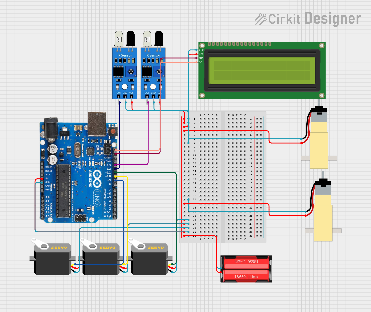
Circuit Documentation
Summary
This circuit involves an Arduino Uno R3 microcontroller interfacing with various components including IR sensors, servos, a hobby gear motor, and a 16x2 I2C LCD. The circuit is powered by a 18650 Li-Ion battery. The Arduino controls the servos and motors based on input from the IR sensors and displays information on the LCD.
Component List
Arduino Uno R3
- Description: A microcontroller board based on the ATmega328P.
- Pins: D8, D9, D10, D11, D12, D13, GND, AREF, SDA, SCL, D0/RX, D1/Tx, D2, D3, D4, D5, 6, D7, A5/SCL, A4/SDA, A3, A2, A1, A0, Vin, 5V, 3.3V, RESET, IOREF, NONE, USB Jack, Power Jack
IR Sensor
- Description: Infrared sensor for object detection.
- Pins: out, gnd, vcc
Hobby Gearmotor with 48:1 Gearbox
- Description: A small DC motor with a 48:1 gearbox.
- Pins: pin 1, pin 2
Servo
- Description: A small servo motor.
- Pins: gnd, vcc, pulse
16x2 I2C LCD
- Description: A 16x2 character LCD with I2C interface.
- Pins: GND, VCC, SDA, SCL
18650 Li-Ion Battery
- Description: A rechargeable lithium-ion battery.
- Pins: Positive, Negative
Wiring Details
Arduino Uno R3
- D9: Connected to Servo (pulse)
- D10: Connected to Servo (pulse)
- D11: Connected to Servo (pulse)
- D12: Connected to IR Sensor (out)
- D13: Connected to IR Sensor (out)
- SDA: Connected to 16x2 I2C LCD (SDA)
- SCL: Connected to 16x2 I2C LCD (SCL)
- GND: Connected to IR Sensor (gnd), IR Sensor (gnd), Hobby Gearmotor (pin 1), 16x2 I2C LCD (GND), Hobby Gearmotor (pin 1), Servo (gnd), Servo (gnd), Servo (gnd), 18650 Li-Ion (Negative)
- 5V: Connected to IR Sensor (vcc), IR Sensor (vcc), 16x2 I2C LCD (VCC), Hobby Gearmotor (pin 2), Hobby Gearmotor (pin 2), Servo (vcc), Servo (vcc), Servo (vcc), 18650 Li-Ion (Positive)
IR Sensor
- out: Connected to Arduino Uno R3 (D12)
- gnd: Connected to Arduino Uno R3 (GND)
- vcc: Connected to Arduino Uno R3 (5V)
IR Sensor
- out: Connected to Arduino Uno R3 (D13)
- gnd: Connected to Arduino Uno R3 (GND)
- vcc: Connected to Arduino Uno R3 (5V)
Hobby Gearmotor with 48:1 Gearbox
- pin 1: Connected to Arduino Uno R3 (GND)
- pin 2: Connected to Arduino Uno R3 (5V)
Hobby Gearmotor with 48:1 Gearbox
- pin 1: Connected to Arduino Uno R3 (GND)
- pin 2: Connected to Arduino Uno R3 (5V)
Servo
- gnd: Connected to Arduino Uno R3 (GND)
- vcc: Connected to Arduino Uno R3 (5V)
- pulse: Connected to Arduino Uno R3 (D9)
Servo
- gnd: Connected to Arduino Uno R3 (GND)
- vcc: Connected to Arduino Uno R3 (5V)
- pulse: Connected to Arduino Uno R3 (D10)
Servo
- gnd: Connected to Arduino Uno R3 (GND)
- vcc: Connected to Arduino Uno R3 (5V)
- pulse: Connected to Arduino Uno R3 (D11)
16x2 I2C LCD
- GND: Connected to Arduino Uno R3 (GND)
- VCC: Connected to Arduino Uno R3 (5V)
- SDA: Connected to Arduino Uno R3 (SDA)
- SCL: Connected to Arduino Uno R3 (SCL)
18650 Li-Ion Battery
- Positive: Connected to Arduino Uno R3 (5V)
- Negative: Connected to Arduino Uno R3 (GND)
Code Documentation
#include <Servo.h>
#include <Wire.h>
#include <LiquidCrystal_I2C.h>

// Pin Definitions
const int IR_SENSOR1_PIN = 12; // IR sensor 1 connected to pin 12
const int IR_SENSOR2_PIN = 13; // IR sensor 2 connected to pin 13
bool sensor1Enabled = true;    // Variable to track if sensor 1 is enabled
bool sensor2Enabled = true;    // Variable to track if sensor 2 is enabled

// Define the servo objects
Servo servo1;  // Claw servo
Servo servo2;  // Body servo
Servo servo3;  // Base servo

// LCD Initialization (I2C address 0x27, 16 columns, 2 rows)
LiquidCrystal_I2C lcd(0x27, 16, 2);

void setup() {
  // Attach the servos to their respective pins
  servo1.attach(9);   // Attach servo1 (claw) to pin 9
  servo2.attach(10);  // Attach servo2 (body) to pin 10
  servo3.attach(11);  // Attach servo3 (base) to pin 11

  // Set motor control pins as output
  pinMode(2, OUTPUT);  // Motor 1 direction pin
  pinMode(5, OUTPUT);  // Motor 1 speed pin
  pinMode(4, OUTPUT);  // Motor 2 direction pin
  pinMode(6, OUTPUT);  // Motor 2 speed pin

  // Set the IR sensor pin mode to input
  pinMode(IR_SENSOR1_PIN, INPUT);
  pinMode(IR_SENSOR2_PIN, INPUT);

  // Initialize LCD
  lcd.init();         // Use init() instead of begin()
  lcd.backlight();    // Turn on the backlight
  lcd.setCursor(0, 0);
  lcd.print("GROUP 7");
  lcd.setCursor(0, 1);
  lcd.print("FINAL PROJECT");
  delay(5000);        // Display welcome message for 5 seconds
  lcd.clear();

  // Initial servo movements with delays
  moveServoSlowly(servo3, 80, 5);  // Move base (servo3) to 80 degrees slowly
  delay(3000);  // Wait for 3 seconds before completing the setup

  moveServoSlowly(servo1, 130, 20);  // Move claw (servo1) to 130 degrees slowly
  delay(3000);  // Wait for 3 seconds before moving the next servo

  moveServoSlowly(servo2, 30, 20);  // Move body (servo2) to 40 degrees slowly
  delay(3000);  // Wait for 3 seconds before moving the next servo

  // Continue with further movements
  moveServoSlowly(servo3, 20, 5);  // Move base (servo3) to 20 degrees slowly
  delay(3000);

  moveServoSlowly(servo2, 120, 20);  // Move body (servo2) to 110 degrees slowly
  delay(3000);

  moveServoSlowly(servo1, 190, 20);  // Move claw (servo1) to 190 degrees slowly
  delay(3000);

  moveServoSlowly(servo2, 30, 20);  // Move body (servo2) back to 40 degrees slowly
  delay(4000);

  moveServoSlowly(servo3, 50, 5);  // Move base (servo3) to 50 degrees slowly
  delay(3000);

  moveServoSlowly(servo2, 120, 20);  // Move body (servo2) to 110 degrees slowly
  delay(3000);

  moveServoSlowly(servo1, 130, 20);  // Move claw (servo1) back to 130 degrees slowly
  delay(1000);

  moveServoSlowly(servo2, 30, 20);  // Move body (servo2) back to 40 degrees slowly
  delay(3000);

  moveServoSlowly(servo3, 80