
Wi-Fi Controlled Smart Sensor System with NodeMCU, Ultrasonic Sensor, and I2C LCD
View and Edit Project In Cirkit Designer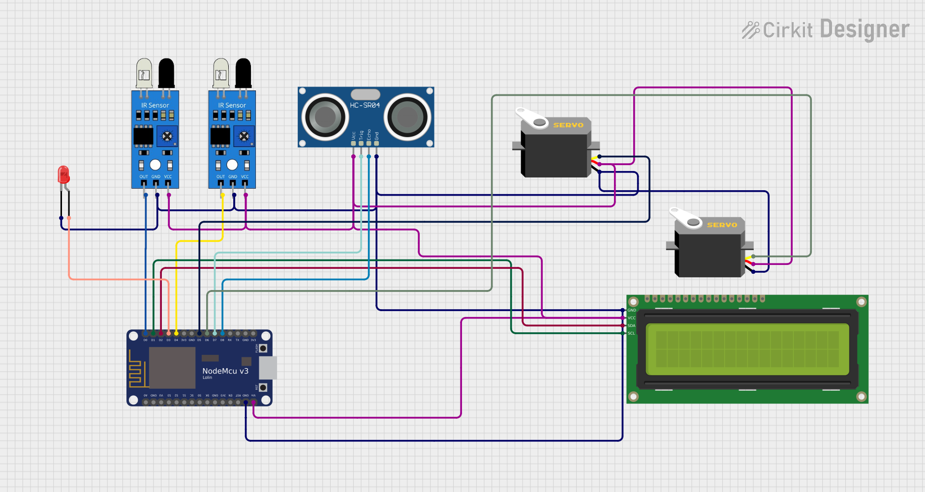
Circuit Documentation
Summary
This document provides a detailed overview of a circuit that includes an HC-SR04 Ultrasonic Sensor, a 16x2 I2C LCD, a NodeMCU V3 ESP8266, two IR sensors, two Servos, and a red LED. The circuit is designed to interface these components with the NodeMCU for various sensing and display purposes.
Component List
HC-SR04 Ultrasonic Sensor
- Description: Ultrasonic distance sensor
- Pins: VCC, TRIG, ECHO, GND
16x2 I2C LCD
- Description: 16x2 character LCD with I2C interface
- Pins: GND, VCC, SDA, SCL
NodeMCU V3 ESP8266
- Description: Wi-Fi enabled microcontroller
- Pins: A0, GND, VU, S3, S2, S1, SC, S0, SK, 3V3, EN, RST, Vin, D0, D1, D2, D3, D4, D5, D6, D7, D8, RX, TX
Servo (x2)
- Description: Servo motor
- Pins: gnd, vcc, pulse
IR Sensor (x2)
- Description: Infrared sensor
- Pins: out, gnd, vcc
LED: Two Pin (red)
- Description: Red LED
- Pins: cathode, anode
Wiring Details
HC-SR04 Ultrasonic Sensor
- VCC connected to NodeMCU Vin
- TRIG connected to NodeMCU D7
- ECHO connected to NodeMCU D8
- GND connected to NodeMCU GND
16x2 I2C LCD
- GND connected to NodeMCU GND
- VCC connected to NodeMCU Vin
- SDA connected to NodeMCU D2
- SCL connected to NodeMCU D1
NodeMCU V3 ESP8266
- Vin connected to:
- HC-SR04 Ultrasonic Sensor VCC
- 16x2 I2C LCD VCC
- IR Sensor VCC (both sensors)
- Servo VCC (both servos)
- GND connected to:
- HC-SR04 Ultrasonic Sensor GND
- 16x2 I2C LCD GND
- IR Sensor GND (both sensors)
- Servo GND (both servos)
- LED cathode
- D0 connected to IR Sensor out
- D1 connected to 16x2 I2C LCD SCL
- D2 connected to 16x2 I2C LCD SDA
- D3 connected to LED anode
- D4 connected to IR Sensor out
- D5 connected to Servo pulse
- D6 connected to Servo pulse
- D7 connected to HC-SR04 Ultrasonic Sensor TRIG
- D8 connected to HC-SR04 Ultrasonic Sensor ECHO
Servo (1)
- gnd connected to NodeMCU GND
- vcc connected to NodeMCU Vin
- pulse connected to NodeMCU D5
Servo (2)
- gnd connected to NodeMCU GND
- vcc connected to NodeMCU Vin
- pulse connected to NodeMCU D6
IR Sensor (1)
- out connected to NodeMCU D0
- gnd connected to NodeMCU GND
- vcc connected to NodeMCU Vin
IR Sensor (2)
- out connected to NodeMCU D4
- gnd connected to NodeMCU GND
- vcc connected to NodeMCU Vin
LED: Two Pin (red)
- cathode connected to NodeMCU GND
- anode connected to NodeMCU D3
Code
No code provided for this circuit.
This documentation provides a comprehensive overview of the components and their connections in the circuit. Each component is described, and detailed wiring instructions are provided to ensure correct assembly.