
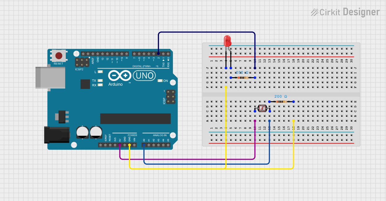
Circuit Documentation
Summary of the Circuit
This circuit is designed to use an Arduino UNO to read the light intensity from a photocell (Light Dependent Resistor, LDR) and control an LED based on the light level. When the light level falls below a certain threshold, the LED is turned on, indicating low light conditions. The circuit includes a photocell, two resistors, and an LED. The Arduino UNO is programmed to read the analog value from the photocell and control the LED accordingly.
Component List
Arduino UNO
- Description: A microcontroller board based on the ATmega328P.
- Pins: UNUSED, IOREF, Reset, 3.3V, 5V, GND, Vin, A0-A5, SCL, SDA, AREF, D0-D13.
- Purpose: Acts as the central processing unit of the circuit, reading sensor data and controlling the LED.
LED: Two Pin (red)
- Description: A basic red light-emitting diode.
- Pins: cathode, anode.
- Purpose: Provides a visual indication of the light level as detected by the photocell.
Resistor (200 Ohms)
- Description: A resistor with a resistance of 200 Ohms.
- Pins: pin1, pin2.
- Purpose: Limits the current flowing through the LED to prevent damage.
Photocell (LDR)
- Description: A light-dependent resistor whose resistance changes with light intensity.
- Pins: pin 0, pin 1.
- Purpose: Senses the ambient light level to control the LED.
Wiring Details
Arduino UNO
- 5V connected to Photocell (LDR) pin 0.
- GND connected to one side of a 200 Ohm Resistor, which is then connected to the cathode of the LED.
- A0 connected to the junction between the Photocell (LDR) pin 1 and the other 200 Ohm Resistor pin1.
- D2 connected to the anode of the LED through another 200 Ohm Resistor.
LED: Two Pin (red)
- Cathode connected to GND through a 200 Ohm Resistor.
- Anode connected to D2 on the Arduino UNO through another 200 Ohm Resistor.
Resistor (200 Ohms)
- One Resistor is connected between the GND of the Arduino UNO and the cathode of the LED.
- Another Resistor is connected between the A0 of the Arduino UNO and the pin 1 of the Photocell (LDR).
Photocell (LDR)
- Pin 0 connected to 5V on the Arduino UNO.
- Pin 1 connected to A0 on the Arduino UNO through a 200 Ohm Resistor.
Documented Code
// Code for Arduino UNO
int photocellPin = 0; // Analog pin A0
int ledPin = 2;       // Digital pin D2
int photocellReading;  // Variable to store the value from the photocell
const float limit = 100; // Threshold for turning the LED on

void setup() {
  Serial.begin(9600);  // Start serial communication at 9600 baud
  pinMode(ledPin, OUTPUT); // Set the LED pin as an output
}

void loop() {
  photocellReading = analogRead(photocellPin); // Read the value from the photocell
  Serial.print("Analog reading = ");
  Serial.println(photocellReading); // Print the reading to the serial monitor

  if (photocellReading < limit) {
    digitalWrite(ledPin, HIGH); // If the reading is below the limit, turn on the LED
  } else {
    digitalWrite(ledPin, LOW); // Otherwise, turn off the LED
  }
  delay(1000); // Wait for a second before reading again
}
This code is designed to be uploaded to the Arduino UNO microcontroller. It initializes the serial communication for debugging purposes and sets the LED pin as an output. In the main loop, it reads the analog value from the photocell and prints it to the serial monitor. Depending on the value read, it turns the LED on or off.