
Circuit Documentation
Summary
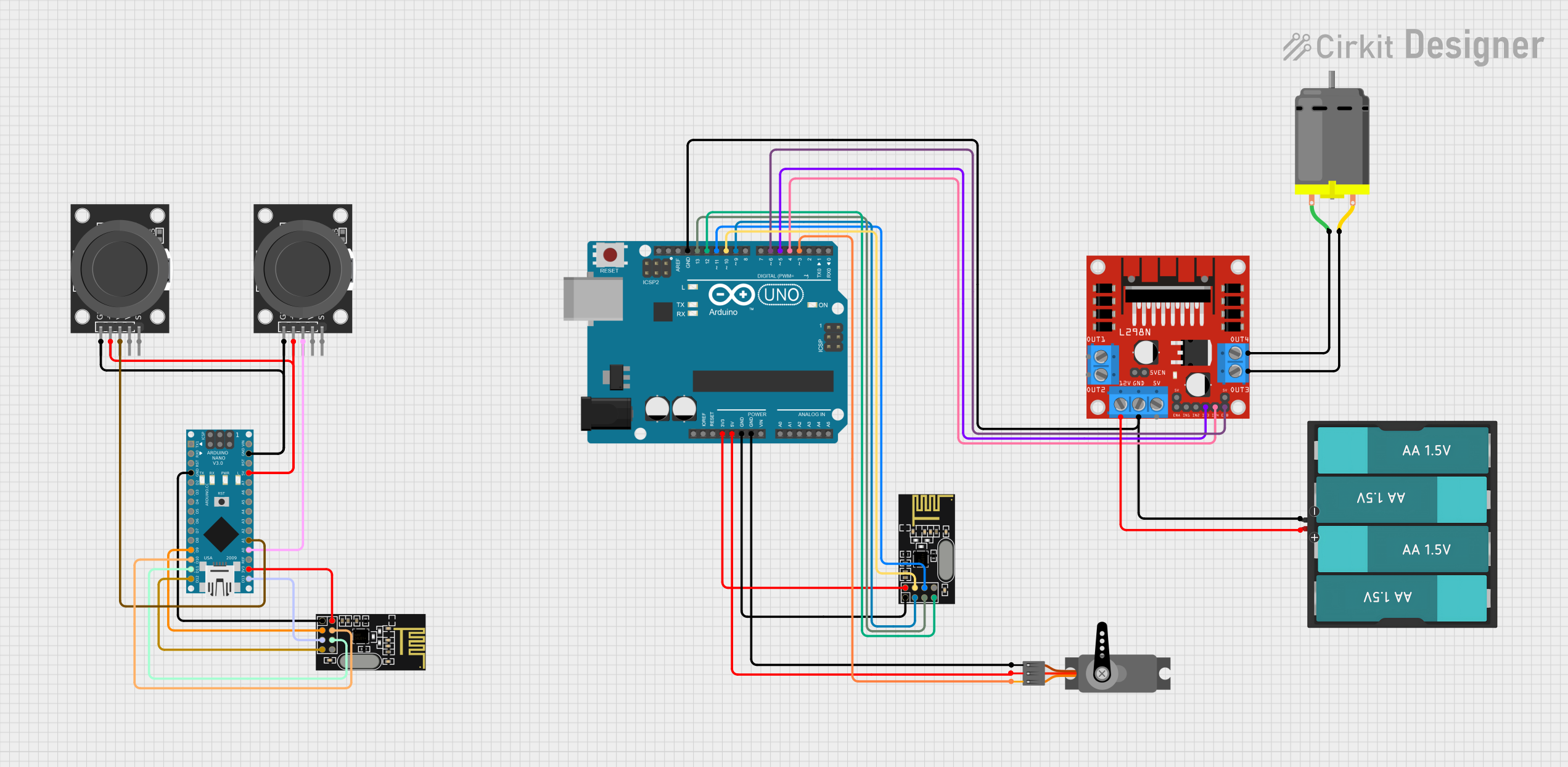
This circuit is designed to facilitate wireless communication between two microcontroller units (MCUs) using NRF24L01 transceiver modules. The primary MCU, an Arduino UNO, controls a servo motor and a DC motor via an L298N motor driver. The secondary MCU, an Arduino Nano, interfaces with two KY-023 Dual Axis Joystick Modules to capture user inputs. The Arduino UNO receives the joystick positions wirelessly and translates them into motor control signals. The DC motor's speed and direction are controlled by the L298N driver, while the servo's position is adjusted directly by the Arduino UNO.
Component List
Microcontrollers
- Arduino UNO: A microcontroller board based on the ATmega328P, featuring digital and analog I/O pins.
- Arduino Nano: A compact microcontroller board based on the ATmega328, similar to the UNO but smaller in size.
Communication Modules
- NRF24L01: A 2.4GHz wireless transceiver module used for short-range wireless communication between the two MCUs.
Motor and Driver
- DC Motor: An electric motor that converts electrical energy into mechanical rotation.
- L298N DC Motor Driver: A dual H-bridge motor driver capable of driving two DC motors or one stepper motor.
Power Supply
- Battery AAx4 6V: A battery pack consisting of four AA batteries providing a 6V power supply.
Actuators
- Servo: An actuator capable of precise angular positioning, commonly used for steering mechanisms in robotics.
Sensors and Input Devices
- KY-023 Dual Axis Joystick Module: An input device with two potentiometers for capturing bidirectional (X and Y axis) analog input.
Wiring Details
Arduino UNO
- 3.3V to NRF24L01 VCC (3V)
- 5V to Servo VCC
- GND to NRF24L01 GND, Servo GND, Battery GND, L298N GND
- D13 to NRF24L01 SCK
- D12 to NRF24L01 MISO
- D11 to NRF24L01 MOSI
- D10 to NRF24L01 CSN
- D9 to NRF24L01 CE
- D6 to L298N ENB
- D5 to L298N IN3
- D4 to L298N IN4
- D3 to Servo PWM
L298N DC Motor Driver
- 12V to Battery VCC
- OUT3 to DC Motor pin 2
- OUT4 to DC Motor pin 1
Arduino Nano
- 5V to KY-023 Joystick Modules +5V
- GND to NRF24L01 GND, KY-023 Joystick Modules GND
- 3V3 to NRF24L01 VCC (3V)
- D13/SCK to NRF24L01 SCK
- D12/MISO to NRF24L01 MISO
- D11/MOSI to NRF24L01 MOSI
- D10 to NRF24L01 CSN
- D9 to NRF24L01 CE
- A1 to KY-023 Joystick Module VRx
- A0 to KY-023 Joystick Module VRx (second module)
KY-023 Dual Axis Joystick Module
- +5V to Arduino Nano 5V
- GND to Arduino Nano GND
- VRx to Arduino Nano A1 (first module), A0 (second module)
Documented Code
Arduino UNO Code
#include <SPI.h>
#include <nRF24L01.h>
#include <RF24.h>
#include <Servo.h>

Servo myservo;

// Set the CE and CSN pins
RF24 radio(9, 10);

// Create a pipe for communication
const byte address[6] = "00001";

int motorPin1 = 4;
int motorPin2 = 5;
int mappedServoValue;
int mappedMotorValue;

// Structure to hold the received variables
struct DataPackage {
  int motorValue;
  int servoValue;
};

DataPackage data;

void setup() {
  Serial.begin(9600);
  myservo.attach(3);

  pinMode(5, OUTPUT);
  pinMode(4, OUTPUT);

  digitalWrite(motorPin1, HIGH);
  digitalWrite(motorPin2, LOW);

  // Initialize the NRF24L01 module
  radio.begin();

  // Open the same pipe as the transmitter for reading
  radio.openReadingPipe(0, address);

  // Set the radio in receiver mode
  radio.setPALevel(RF24_PA_MIN);
  radio.startListening(); // Start listening for data
}

void loop() {
  if (radio.available()) { // Check if data is available
    radio.read(&data, sizeof(data)); // Read the incoming data structure

    mappedMotorValue = map(data.motorValue,500,1023,0,255);
    if (data.motorValue > 510) {
      analogWrite(6,mappedMotorValue);
    }
    else {
      analogWrite(6,0);
    }

    mappedServoValue = map(data.servoValue,0,1023,180,0);
    if (mappedServoValue >= 0){
      myservo.write(mappedServoValue);
    }
    else {
      myservo.write(90);
    }

    // Print the received variables
    Serial.print("MOTOR: ");
    Serial.print(data.motorValue);
    Serial.print(" -> ");
    Serial.print(mappedMotorValue);
    Serial.print("   \tSERVO: ");
    Serial.print(data.servoValue);
    Serial.print(" -> ");
    Serial.println(mappedServoValue);
  }
}
Arduino Nano Code
#include <SPI.h>
#include <nRF24L01.h>
#include <RF24.h>

// Set the CE and CSN pins
RF24 radio(9, 10);

// Create a pipe for communication
const byte address[6] = "00001";

// Structure to hold the received variables
struct DataPackage {
  int motorValue;
  int servoValue;
};

DataPackage data;

#define MOTOR_PIN  A4 // Arduino pin connected to VRX pin
#define SERVO_PIN  A3 // Arduino pin connected to VRY pin

int xValue = 0; // To store value of the X axis
int yValue = 0; // To store value of the Y axis

void setup() {
  Serial.begin(9600) ;

  // Initialize the NRF24L01 module
  radio.begin();

  // Set the address to the pipe for writing
  radio.openWritingPipe(address);

  // Set the radio in transmitter mode
  radio.setPALevel(RF24_PA_MIN);
}

void loop() {
  // read analog X and Y analog values
  data.motorValue = analogRead(MOTOR_PIN);
  data.servoValue = analogRead(SERVO_PIN);

  // Set module to transmit mode
  radio.stopListening();

  // Send the data structure
  bool success = radio.write(&data, sizeof(data));

  if (success) {
    Serial.print("[SENT]\t");
  } else {
    Serial.print("[NOT SENT]\t");
  }

  // print data to Serial Monitor on Arduino IDE
  Serial.print("MOTOR: ");
  Serial.print(data.motorValue);
  Serial.print("\tSERVO: ");
  Serial.println(data.servoValue);

  delay(100);
}
This documentation provides an overview of the circuit, including the components used, their wiring connections, and the embedded code for the microcontrollers. The code sections are documented to reflect the functionality of each microcontroller within the circuit.