
Arduino-Controlled Robotics Platform with IR and Sound Sensors
View and Edit Project In Cirkit Designer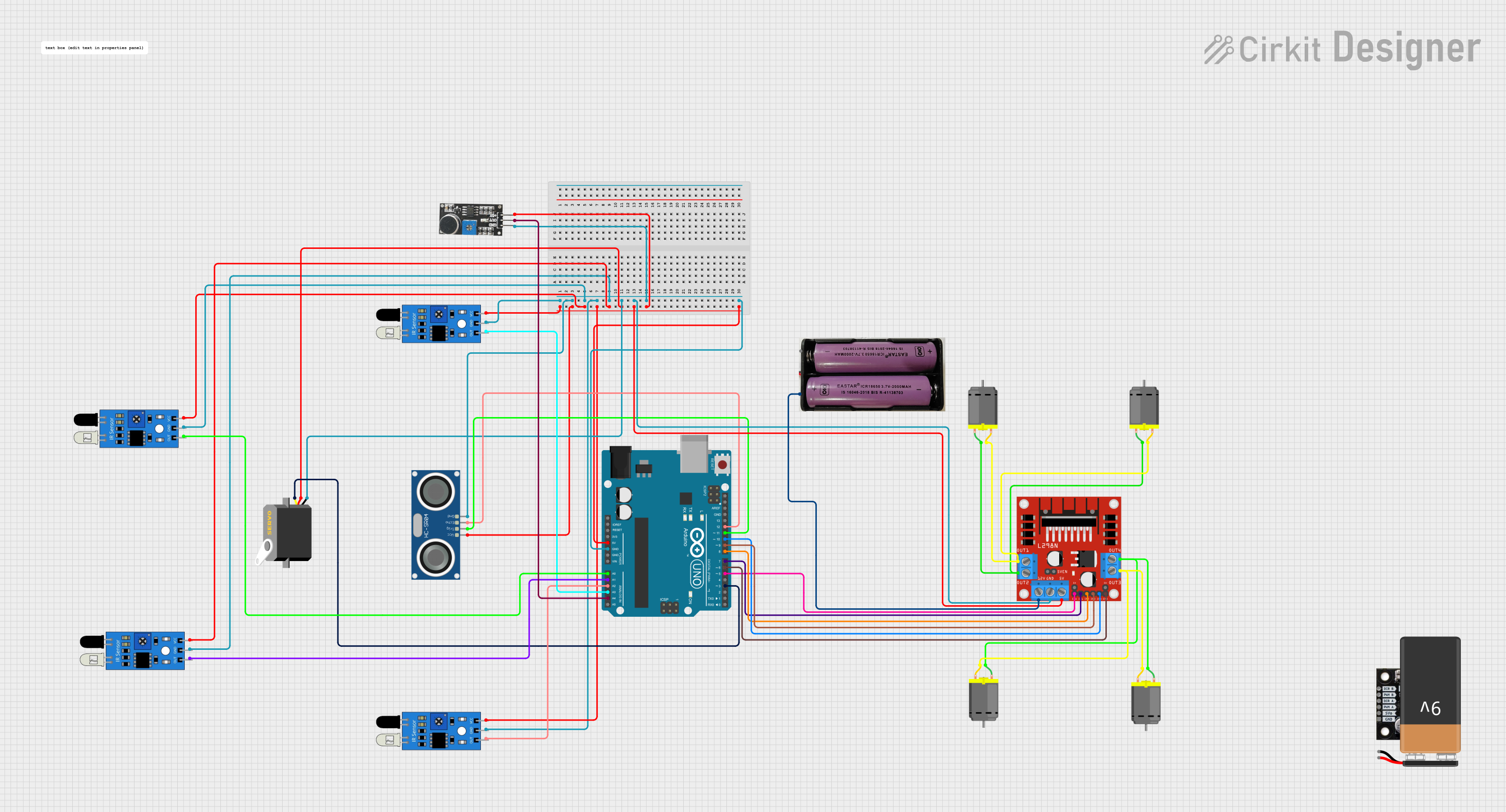
Circuit Documentation
Summary
The circuit in question is designed to interface multiple sensors and actuators with an Arduino UNO microcontroller. The sensors include multiple IR sensors and a sound sensor for input detection, as well as an HC-SR04 ultrasonic sensor for distance measurement. Actuation is handled by a set of DC motors controlled via an L298N DC motor driver, and a servo motor. Power distribution is managed through connections to a 5V supply from the Arduino and a separate 7.4V power source for the motor driver. The circuit is likely intended for a robotics application, given the presence of motion and environmental sensors, along with motor control capabilities.
Component List
IR Sensor
- Pins: out, gnd, vcc
- Description: An infrared sensor capable of detecting proximity or measuring intensity of IR light.
Motor Driver 2 Channel (L298N)
- Pins: DIR B, PWM B, DIR A, PWM A, 5Vo, GND, B+, B-, A-, A+, VM
- Description: A dual H-bridge motor driver that can control the direction and speed of two DC motors.
DC Motor
- Pins: pin 1, pin 2
- Description: A standard DC motor used for creating rotational motion.
Sound Sensor
- Pins: 5V +, OUT, GND
- Description: A sensor that detects the intensity of sound in the environment.
Servo
- Pins: gnd, vcc, pulse
- Description: A rotary actuator or linear actuator that allows for precise control of angular or linear position.
Arduino UNO
- Pins: UNUSED, IOREF, Reset, 3.3V, 5V, GND, Vin, A0, A1, A2, A3, A4, A5, SCL, SDA, AREF, D13, D12, D11, D10, D9, D8, D7, D6, D5, D4, D3, D2, D1, D0
- Description: A microcontroller board based on the ATmega328P, widely used for building digital devices and interactive objects.
HC-SR04 Ultrasonic Sensor
- Pins: VCC, TRIG, ECHO, GND
- Description: A sensor that measures distance by emitting ultrasonic waves and detecting the reflection.
9V Battery
- Pins: -, +
- Description: A standard 9V battery used as a power source.
L298N DC Motor Driver
- Pins: OUT1, OUT2, 12V, GND, 5V, OUT3, OUT4, 5V-ENA-JMP-I, 5V-ENA-JMP-O, +5V-J1, +5V-J2, ENA, IN1, IN2, IN3, IN4, ENB
- Description: A high current dual full-bridge driver designed to accept standard TTL logic levels.
7.4V Battery
- Pins: +, -
- Description: A 7.4V battery used to power motors or other components requiring higher voltage.
Wiring Details
IR Sensors
- VCC: Connected to 5V supply from Arduino UNO.
- GND: Connected to ground (GND) on Arduino UNO.
- OUT: Each sensor's output connected to individual analog input pins (A0, A1, A2, A3) on Arduino UNO.
Motor Driver 2 Channel (L298N)
- 5V: Connected to 5V supply from Arduino UNO.
- GND: Connected to ground (GND) on Arduino UNO.
- IN1, IN2, IN3, IN4: Control inputs connected to digital pins (D7, D8, D9, D10) on Arduino UNO.
- ENA, ENB: Enable pins for motor channels connected to digital pins (D5, D6) on Arduino UNO.
- OUT1, OUT2, OUT3, OUT4: Outputs connected to DC Motors.
DC Motors
- Motors are connected in pairs to the outputs of the L298N motor driver.
Sound Sensor
- 5V +: Connected to 5V supply from Arduino UNO.
- GND: Connected to ground (GND) on Arduino UNO.
- OUT: Output connected to analog input pin (A4) on Arduino UNO.
Servo
- VCC: Connected to 5V supply from Arduino UNO.
- GND: Connected to ground (GND) on Arduino UNO.
- PULSE: Control signal connected to digital pin (D3) on Arduino UNO.
HC-SR04 Ultrasonic Sensor
- VCC: Connected to 5V supply from Arduino UNO.
- GND: Connected to ground (GND) on Arduino UNO.
- TRIG: Trigger pin connected to digital pin (D11) on Arduino UNO.
- ECHO: Echo pin connected to digital pin (D12) on Arduino UNO.
9V Battery
- Not directly connected in the provided net list.
L298N DC Motor Driver
- 12V: Connected to 7.4V battery.
- GND: Connected to ground (GND) on Arduino UNO.
- Control inputs and outputs as described above.
7.4V Battery
- +: Connected to 12V input on L298N motor driver.
- -: Connected to ground (GND) on L298N motor driver.
Documented Code
Arduino UNO (dcc65c53-2cb2-4cfa-b730-e591371713ac)
void setup() {
  // put your setup code here, to run once:

}

void loop() {
  // put your main code here, to run repeatedly:

}
The provided code is a template with empty setup() and loop() functions, which are the standard structure for Arduino sketches. The setup() function is intended to contain code that should run once when the microcontroller is reset or powered on, such as pin mode declarations. The loop() function is for code that should run continuously as long as the microcontroller is powered.