
Circuit Documentation
Summary
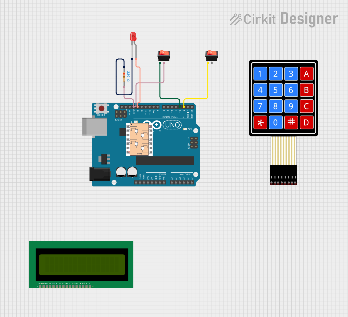
This circuit is designed to demonstrate a NAND gate operation using an Arduino UNO. The circuit includes two rocker switches as inputs, a red LED as the output, and a resistor to limit the current through the LED. The Arduino UNO reads the states of the rocker switches, performs the NAND operation, and displays the result on the LED. The result is also printed to the serial monitor.
Component List
Arduino UNO
- Description: A microcontroller board based on the ATmega328P.
- Pins: UNUSED, IOREF, Reset, 3.3V, 5V, GND, Vin, A0, A1, A2, A3, A4, A5, SCL, SDA, AREF, D13, D12, D11, D10, D9, D8, D7, D6, D5, D4, D3, D2, D1, D0
Rocker Switch (Switch 1)
- Description: A simple on/off switch.
- Pins: output, input
Rocker Switch (Switch 2)
- Description: A simple on/off switch.
- Pins: output, input
7408
- Description: Quad 2-input AND gate IC.
- Pins: 2, 1, 3, 4, 5, 6, Gnd, Vcc, 8, 9, 10, 11, 12, 13
LED: Two Pin (red)
- Description: A red light-emitting diode.
- Pins: cathode, anode
Resistor
- Description: A 220 Ohm resistor used to limit current.
- Pins: pin1, pin2
- Properties: Resistance: 220 Ohms
16X2 LCD
- Description: A 16x2 character LCD display.
- Pins: VSS, VDD, V0, RS, RW, E, D1, D0, D2, D3, D4, D6, D5, D7, A, K
4X4 Membrane Matrix Keypad
- Description: A 4x4 matrix keypad.
- Pins: R1, R2, R3, R4, C1, C2, C3, C4
Wiring Details
Arduino UNO
GND is connected to:
- Rocker Switch (Switch 1) output
- Resistor pin2
D13 is connected to:
- LED anode
D3 is connected to:
- Rocker Switch (Switch 1) input
D2 is connected to:
- Rocker Switch (Switch 2) input
Rocker Switch (Switch 1)
output is connected to:
- Arduino UNO GND
- Resistor pin2
input is connected to:
- Arduino UNO D3
Rocker Switch (Switch 2)
- input is connected to:
- Arduino UNO D2
7408
- No connections specified in the provided net list.
LED: Two Pin (red)
cathode is connected to:
- Resistor pin1
anode is connected to:
- Arduino UNO D13
Resistor
pin1 is connected to:
- LED cathode
pin2 is connected to:
- Rocker Switch (Switch 1) output
- Arduino UNO GND
16X2 LCD
- No connections specified in the provided net list.
4X4 Membrane Matrix Keypad
- No connections specified in the provided net list.
Code Documentation
/*
 * Project Title: NAND Trainer
 * Description: This code controls the inputs from rocker switches, processes the
 * NAND gate operation, and displays the output on an LED according to the NAND
 * truth table.
 */

// Pin definitions
const int switch1Pin = 2;
const int switch2Pin = 3;
const int ledPin = 13;

void setup() {
  // Set up the switch pins as inputs
  pinMode(switch1Pin, INPUT);
  pinMode(switch2Pin, INPUT);
  // Set up the LED pin as an output
  pinMode(ledPin, OUTPUT);
}

void loop() {
  // Read the state of the switches
  int switch1State = digitalRead(switch1Pin);
  int switch2State = digitalRead(switch2Pin);
  // Perform NAND operation
  int nandResult = !(switch1State && switch2State);
  // Display the result on the LED
  digitalWrite(ledPin, nandResult);
  // Print the states and result to the serial monitor
  Serial.begin(9600);
  Serial.print("Switch1: ");
  Serial.print(switch1State ? "HIGH" : "LOW");
  Serial.print(" | Switch2: ");
  Serial.print(switch2State ? "HIGH" : "LOW");
  Serial.print(" | NAND Result: ");
  Serial.println(nandResult ? "HIGH" : "LOW");
  // Small delay to debounce switches
  delay(100);
}
This code sets up the Arduino UNO to read the states of two rocker switches and perform a NAND operation. The result of the NAND operation is displayed on an LED and printed to the serial monitor. The code includes a small delay to debounce the switches.