ESP32-Based GPS Tracker with NEO-6M Module
Circuit Documentation
Summary
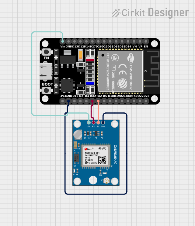
This circuit integrates an ESP32 microcontroller with a Neo 6M GPS Module to receive and process GPS data. The ESP32 is a versatile microcontroller with a variety of I/O pins, and in this circuit, it is used to communicate with the GPS module via serial communication. The GPS module provides location data, which the ESP32 reads and processes to extract information such as latitude, longitude, altitude, speed, and timestamp.
Component List
ESP32 (30 pin)
- Description: A 30-pin microcontroller with WiFi and Bluetooth capabilities.
- Purpose: Acts as the central processing unit for the circuit, handling data communication with the GPS module and processing the received GPS data.
- Pins: EN, VP, VN, D34, D35, D32, D33, D25, D26, D27, D14, D12, D13, GND, Vin, D23, D22, TX0, RX0, D21, D19, D18, D5, TX2, RX2, D4, D2, D15, 3V3
Neo 6M GPS Module
- Description: A GPS receiver module capable of providing accurate location data.
- Purpose: Supplies the circuit with real-time location data, including coordinates and time.
- Pins: GND, TX, RX, VCC
Wiring Details
ESP32 (30 pin)
- Vin: Connected to the VCC of the Neo 6M GPS Module to provide power.
- TX2: Connected to the TX pin of the Neo 6M GPS Module for transmitting data.
- RX2: Connected to the RX pin of the Neo 6M GPS Module for receiving data.
- GND: Connected to the GND of the Neo 6M GPS Module to complete the power circuit.
Neo 6M GPS Module
- VCC: Connected to the Vin of the ESP32 to receive power.
- TX: Connected to the TX2 of the ESP32 for transmitting data.
- RX: Connected to the RX2 of the ESP32 for receiving data.
- GND: Connected to the GND of the ESP32 to complete the power circuit.
Documented Code
The following code is written for the ESP32 microcontroller to interface with the Neo 6M GPS Module. It initializes the serial communication with the GPS module and processes the received data to extract and display the location, altitude, speed, and timestamp information.
#include <TinyGPS++.h>
#include <TinyGPSPlus.h>

#define GPS_BAUDRATE 9600  // The default baudrate of NEO-6M is 9600

TinyGPSPlus gps;  // the TinyGPS++ object

void setup() {
  Serial.begin(9600);
  Serial2.begin(GPS_BAUDRATE); //serial2 for GPS UART

  Serial.println(F("ESP32 - GPS module_Simulation"));
}

void loop() {
  if (Serial2.available() > 0) {
    if (gps.encode(Serial2.read())) {
      if (gps.location.isValid()) {
        Serial.print(F("Latitude: "));
        Serial.println(gps.location.lat(),6);

        Serial.print(F("Longitude: "));
        Serial.println(gps.location.lng(),6);

        Serial.print(F("Altitude: "));
        if (gps.altitude.isValid())
          Serial.println(gps.altitude.meters());
        else
          Serial.println(F("INVALID"));
      } else {
        Serial.println(F("Location: INVALID"));
      }

      Serial.print(F("Speed: "));
      if (gps.speed.isValid()) {
        Serial.print(gps.speed.kmph());
        Serial.println(F(" km/h"));
      } else {
        Serial.println(F("INVALID"));
      }

      Serial.print(F("GPS date&time: "));
      if (gps.date.isValid() && gps.time.isValid()) {
        Serial.print(gps.date.year());
        Serial.print(F("-"));
        Serial.print(gps.date.month());
        Serial.print(F("-"));
        Serial.print(gps.date.day());
        Serial.print(F(" "));
        Serial.print(gps.time.hour());
        Serial.print(F(":"));
        Serial.print(gps.time.minute());
        Serial.print(F(":"));
        Serial.println(gps.time.second());
      } else {
        Serial.println(F("INVALID"));
      }

      Serial.println();
    }
  }

  if (millis() > 5000 && gps.charsProcessed() < 10)
    Serial.println(F("No GPS data received: check wiring"));
}
This code uses the TinyGPS++ library to parse the GPS data. It sets up the ESP32 to communicate with the GPS module over Serial2 at a baud rate of 9600. The loop function continuously checks for available data from the GPS module, decodes it, and prints the location, altitude, speed, and timestamp to the serial monitor. If no data is received within the first 5 seconds, it prompts the user to check the wiring.