
Arduino UNO Based Smart Parking System with IR Sensors and Servo Gate Control
View and Edit Project In Cirkit Designer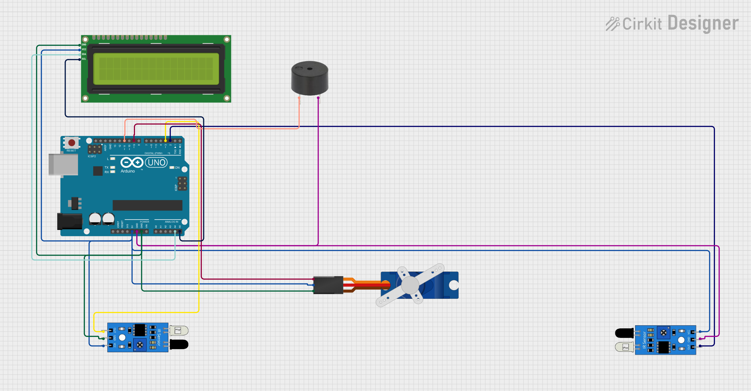
Circuit Documentation
Summary
The circuit in question is designed to manage a smart parking system. It utilizes an Arduino UNO as the central microcontroller to interface with various components including two IR sensors, a Tower Pro SG90 servo motor, a buzzer, and an I2C LCD 16x2 screen. The IR sensors are used to detect the entry and exit of cars, the servo motor acts as a barrier control, the buzzer provides audible alerts, and the LCD screen displays parking information. The Arduino UNO controls the logic of the system, processes sensor inputs, drives the servo and buzzer, and communicates with the LCD via the I2C protocol.
Component List
Arduino UNO
- Microcontroller board based on the ATmega328P
- Features digital I/O pins, analog input pins, and various power pins
- Utilized for controlling the overall logic of the smart parking system
IR Sensors (2x)
- Infrared sensors used for detecting the presence of objects (cars in this case)
- Each sensor has an output, ground, and VCC pin
Tower Pro SG90 Servo
- A small and lightweight servo motor
- Used for moving the parking barrier
- Has signal, power (+5V), and ground pins
Buzzer
- An electronic buzzer for audible alerts
- Has a signal pin and a ground pin
I2C LCD 16x2 Screen
- A 16x2 character LCD display with an I2C interface
- Displays parking information such as the number of cars inside and status messages
- Has SCL, SDA, VCC, and GND pins for communication and power
Wiring Details
Arduino UNO
- 5V pin connected to the VCC pins of both IR sensors, the servo motor, and the I2C LCD screen
- GND pin connected to the ground pins of one IR sensor and the buzzer
- A4 (SDA) pin connected to the SDA pin of the I2C LCD screen
- A5 (SCL) pin connected to the SCL pin of the I2C LCD screen
- D11 pin connected to the signal pin of the buzzer
- D9 pin connected to the signal pin of the servo motor
- D3 pin connected to the output pin of one IR sensor
- D2 pin connected to the output pin of the other IR sensor
IR Sensors
- VCC pin connected to the 5V supply from the Arduino UNO
- GND pin connected to the ground (one sensor shares GND with the Arduino UNO, the other with the I2C LCD screen and servo motor)
- OUT pin connected to the D2 and D3 pins on the Arduino UNO for sensor data
Tower Pro SG90 Servo
- Signal pin connected to the D9 pin on the Arduino UNO
- +5V pin connected to the 5V supply from the Arduino UNO
- GND pin connected to the ground shared with the I2C LCD screen and one IR sensor
Buzzer
- PIN connected to the D11 pin on the Arduino UNO
- GND connected to the ground on the Arduino UNO
I2C LCD 16x2 Screen
- SDA pin connected to the A4 pin on the Arduino UNO
- SCL pin connected to the A5 pin on the Arduino UNO
- VCC (5V) pin connected to the 5V supply from the Arduino UNO
- GND pin connected to the ground shared with the servo motor and one IR sensor
Documented Code
#include <Servo.h>
#include <Wire.h>
#include <LiquidCrystal_I2C.h>

// Initialize the LCD with I2C address 0x27, 16 columns and 2 rows
LiquidCrystal_I2C lcd(0x27, 16, 2);

// Define the GPIO pins directly
const int servo_pin = 9;   // Servo pin (use pin 9)
const int in_pin = 2;      // Input pin for entering (use pin 2)
const int out_pin = 3;     // Input pin for exiting (use pin 3)
const int buzzer_pin = 11; // Buzzer pin (use pin 11)

// Initialize the servo
Servo myservo;
int count = 0;

void IN() {
    count++;
    lcd.clear();
    lcd.print("CAR INCOMING");
    lcd.setCursor(0, 1);
    lcd.print(count);
    delay(1000);
}

void OUT() {
    count--;
    lcd.clear();
    lcd.print("CAR OUTGOING");
    lcd.setCursor(0, 1);
    lcd.print(count);
    delay(3000);
}

void smoothServoMove(int targetAngle) {
    int currentAngle = myservo.read();
    int step = (targetAngle > currentAngle) ? 1 : -1;

    for (int angle = currentAngle; angle != targetAngle; angle += step) {
        myservo.write(angle);
        delay(15); // Adjust this delay for speed of movement
    }
}

void setup() {
    // Initialize the LCD
    lcd.init();
    lcd.backlight();

    // Initialize serial communication
    Serial.begin(115200);

    // Set up pin modes
    pinMode(in_pin, INPUT_PULLUP);
    pinMode(out_pin, INPUT_PULLUP);
    pinMode(buzzer_pin, OUTPUT); // Initialize buzzer pin

    // Initial LCD message
    lcd.setCursor(0, 0);
    lcd.print("SMART PARKING ");
    delay(1000);

    lcd.clear();
    lcd.print("CAR INSIDE");
    lcd.setCursor(0, 1);
    lcd.print(count);

    // Attach the servo
    myservo.attach(servo_pin, 500, 2400);
}

void loop() {
    // Check input pins and update count
    if (digitalRead(in_pin) == LOW) {
        IN();
    }
    if (digitalRead(out_pin) == LOW) {
        OUT();
    }

    // Check count and control servo and buzzer
    if (count >= 10) {
        lcd.clear();
        lcd.print("PLEASE WAIT....");
        lcd.setCursor(0, 1);
        lcd.print("LIMIT IS Full");

        smoothServoMove(100);           // Move to open position (100 degrees)
        tone(buzzer_pin, 1000);        // Start buzzer at 1000 Hz
    } else {
        smoothServoMove(0);             // Move to closed position (0 degrees)
        noTone(buzzer_pin);             // Stop buzzer
    }

    delay(100);  // Short delay to reduce flicker and CPU usage
}
This code is responsible for controlling the smart parking system. It initializes the LCD screen, sets up the GPIO pins, and defines the behavior for car entry and exit. The servo motor is controlled to act as a barrier, and the buzzer provides audible feedback when the parking limit is reached. The LCD screen displays the current status and the number of cars inside the parking area.