
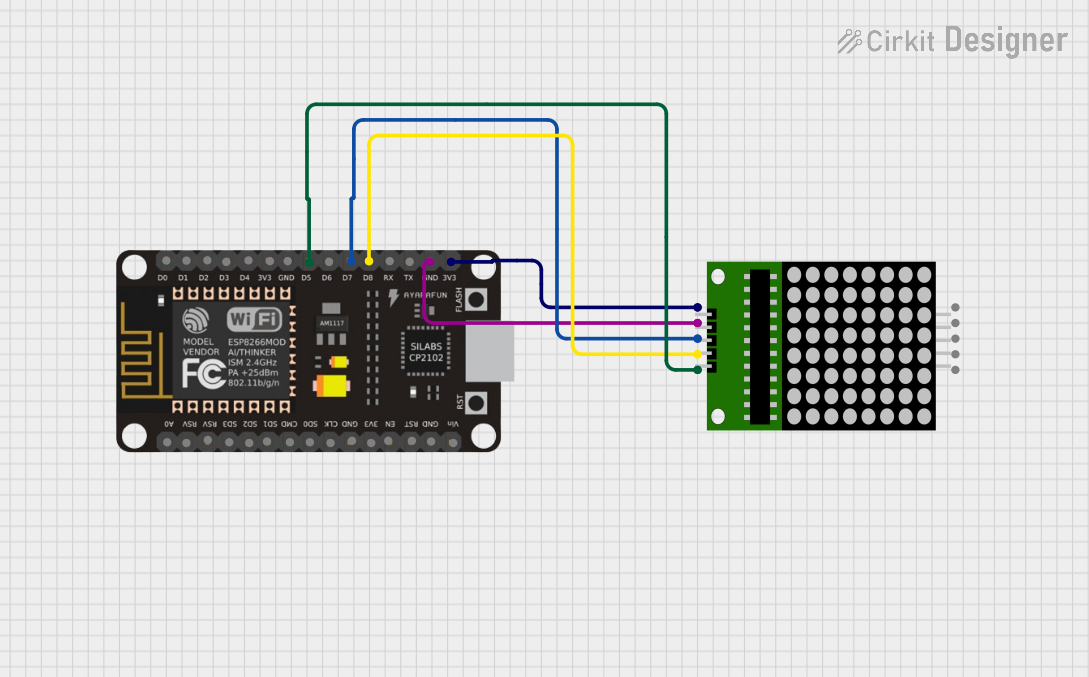
Circuit Documentation
Summary of the Circuit
This circuit integrates an ESP8266 NodeMCU microcontroller with an 8x8 LED matrix display. The ESP8266 NodeMCU serves as the primary controller, capable of driving the LED matrix to display patterns or characters. The 8x8 matrix is a grid of LEDs that can be individually controlled by the microcontroller through a serial interface, allowing for a variety of visual outputs.
Component List
ESP8266 NodeMCU
- Description: A Wi-Fi enabled microcontroller module with a wide range of GPIO pins for interfacing with various peripherals.
- Pins: D0, D1, D2, D3, D4, 3V3, GND, D5, D6, D7, D8, RX, TX, A0, RSV, SD3, SD2, SD1, CMD, SD0, CLK, EN, RST, VIN
8x8 LED Matrix
- Description: A display module consisting of 64 LEDs arranged in an 8x8 grid, which can be controlled to display information or patterns.
- Pins: VCC, DIN, CLK, CS, GND
Wiring Details
ESP8266 NodeMCU
- D5: Connected to CS (Chip Select) of the 8x8 LED Matrix.
- D7: Connected to DIN (Data In) of the 8x8 LED Matrix.
- D8: Connected to CLK (Clock) of the 8x8 LED Matrix.
- GND: Connected to GND (Ground) of the 8x8 LED Matrix.
- 3V3: Connected to VCC (Power) of the 8x8 LED Matrix.
8x8 LED Matrix
- CS: Connected to D5 of the ESP8266 NodeMCU.
- DIN: Connected to D7 of the ESP8266 NodeMCU.
- CLK: Connected to D8 of the ESP8266 NodeMCU.
- GND: Connected to GND of the ESP8266 NodeMCU.
- VCC: Connected to 3V3 of the ESP8266 NodeMCU.
Documented Code
No code has been provided for the microcontroller. To operate the 8x8 LED Matrix, code should be written and uploaded to the ESP8266 NodeMCU. The code should initialize the necessary pins and implement a communication protocol to send data to the LED matrix. Typically, this would involve setting up a SPI interface or bit-banging the serial protocol to control the matrix.