
MakerEdu Creator with Bluetooth, IR Sensors, LCD Display, and Push Button Interaction
View and Edit Project In Cirkit Designer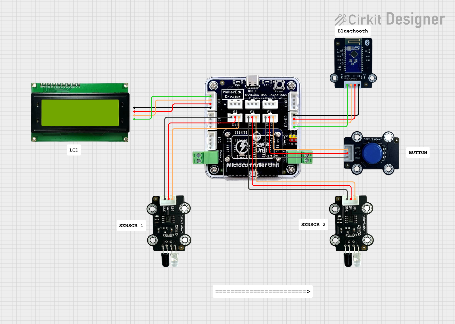
Circuit Documentation
Summary of the Circuit
This circuit is designed to interface various components with a MakerEdu Creator microcontroller board. The circuit includes two MKE-S11 IR Infrared Obstacle Avoidance Sensors for detecting obstacles, an MKE-M02 Push Button Tact Switch Module for user input, an MKE-M15 Bluetooth module for wireless communication, and an MKE-M08 LCD2004 I2C Module for display purposes. The circuit is powered by a 5V supply from the MakerEdu Creator board, which also provides ground connections to all components. Communication between the microcontroller and the Bluetooth module is achieved through serial communication (RX/TX), while the LCD module communicates via the I2C protocol (SCL/SDA). The obstacle sensors and push button are connected to digital input pins on the microcontroller.
Component List
MakerEdu Creator
- Microcontroller board with various digital and analog I/O pins, I2C, serial communication, and power pins.
MKE-S11 IR Infrared Obstacle Avoidance Sensor (x2)
- Sensors that detect the presence of an obstacle using infrared light.
MKE-M02 Push Button Tact Switch Module
- A module with a push button switch that provides a digital signal when pressed.
MKE-M15 Bluetooth
- A Bluetooth module that allows for wireless communication with the microcontroller.
MKE-M08 LCD2004 I2C Module
- An LCD display module that communicates with the microcontroller via the I2C protocol.
Wiring Details
MakerEdu Creator
- SCL: Connected to the SCL pin of the MKE-M08 LCD2004 I2C Module.
- SDA: Connected to the SDA pin of the MKE-M08 LCD2004 I2C Module.
- 5V: Provides power to all components requiring 5V.
- GND: Common ground for all components.
- RX: Connected to the TX pin of the MKE-M15 Bluetooth module.
- TX: Connected to the RX pin of the MKE-M15 Bluetooth module.
- D2: Connected to the TX pin of the MKE-M15 Bluetooth module.
- D3: Connected to the RX pin of the MKE-M15 Bluetooth module.
- D10: Connected to the SIG pin of one MKE-S11 IR Infrared Obstacle Avoidance Sensor.
- D11: Connected to the SIG pin of the other MKE-S11 IR Infrared Obstacle Avoidance Sensor.
- D12: Connected to the SIG pin of the MKE-M02 Push Button Tact Switch Module.
MKE-S11 IR Infrared Obstacle Avoidance Sensor
- SIG: Connected to either D10 or D11 on the MakerEdu Creator.
- 5V: Powered by the 5V pin on the MakerEdu Creator.
- GND: Connected to the GND pin on the MakerEdu Creator.
MKE-M02 Push Button Tact Switch Module
- SIG: Connected to D12 on the MakerEdu Creator.
- 5V: Powered by the 5V pin on the MakerEdu Creator.
- GND: Connected to the GND pin on the MakerEdu Creator.
MKE-M15 Bluetooth
- RX: Connected to D3 on the MakerEdu Creator.
- TX: Connected to D2 on the MakerEdu Creator.
- 5V: Powered by the 5V pin on the MakerEdu Creator.
- GND: Connected to the GND pin on the MakerEdu Creator.
MKE-M08 LCD2004 I2C Module
- SCL: Connected to the SCL pin on the MakerEdu Creator.
- SDA: Connected to the SDA pin on the MakerEdu Creator.
- 5V: Powered by the 5V pin on the MakerEdu Creator.
- GND: Connected to the GND pin on the MakerEdu Creator.
Documented Code
No code was provided for the microcontrollers in the circuit. The documentation of the code would typically include descriptions of the functionality implemented, setup and loop functions, and any functions or libraries used to control the components in the circuit. Since no code is available, this section cannot be completed.