
Arduino-Controlled Dual Load Cell Interface with Motor and Servo Actuation
View and Edit Project In Cirkit Designer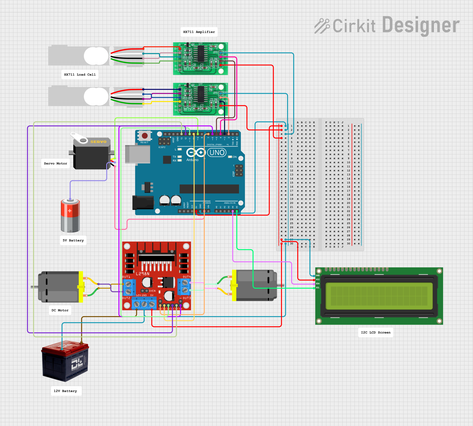
Circuit Documentation
Summary
This circuit is designed to interface various components with an Arduino UNO microcontroller. The circuit includes a DC motor controlled by an L298N motor driver, two load cells interfaced with HX711 bridge sensor interfaces, a servo motor, an I2C LCD 16x2 screen for display, and power sources including a 5V battery and a 12V battery. The Arduino UNO manages the communication and control logic for the entire system.
Component List
DC Motor
- Description: A standard DC motor used for converting electrical energy into mechanical motion.
- Pins: pin 1, pin 2
Arduino UNO
- Description: A microcontroller board based on the ATmega328P, widely used for building digital devices and interactive objects.
- Pins: UNUSED, IOREF, Reset, 3.3V, 5V, GND, Vin, A0-A5, SCL, SDA, AREF, D0-D13
Load Cell - Red/white/black/green
- Description: A transducer that converts force into an electrical signal.
- Pins: E+, A-, E-, A+
HX711 - Bridge Sensor Interface
- Description: A precision 24-bit analog-to-digital converter (ADC) designed for weigh scales and industrial control applications to interface directly with a bridge sensor.
- Pins: E+, E-, A-, A+, B-, B+, GND - GROUND, DATA (OUT), SCK - CLOCK (IN), 3.3/3.5V Supply
Servo
- Description: A rotary actuator or linear actuator that allows for precise control of angular or linear position, velocity, and acceleration.
- Pins: gnd, vcc, pulse
5v Battery
- Description: A power source providing a 5V output, typically used to power electronic components.
- Pins: +, -
L298N DC motor driver
- Description: A high-power motor driver module that allows controlling the speed and direction of two DC motors simultaneously.
- Pins: OUT1, OUT2, 12V, GND, 5V, OUT3, OUT4, 5V-ENA-JMP-I, 5V-ENA-JMP-O, +5V-J1, +5V-J2, ENA, IN1, IN2, IN3, IN4, ENB
Battery 12v
- Description: A power source providing a 12V output, typically used to power motors and other high-power components.
- Pins: -, +
I2C LCD 16x2 Screen
- Description: A liquid crystal display capable of displaying 16 characters per line in 2 lines, interfaced via the I2C protocol.
- Pins: SCL, SDA, VCC (5V), GND, VDD, VO, RS, RW, E, D0-D7, BLA, BLK
Wiring Details
DC Motor
- Wiring:
- pin 1: Connected to L298N DC motor driver OUT3 or OUT1
- pin 2: Connected to L298N DC motor driver OUT4 or OUT2
Arduino UNO
- Wiring:
- 5V: Powers HX711 interfaces, I2C LCD screen, and L298N motor driver
- GND: Common ground for HX711 interfaces, I2C LCD screen, L298N motor driver, and 12V battery
- A4: Connected to I2C LCD screen SDA
- A5: Connected to I2C LCD screen SCL
- D2-D13: Control signals for HX711 interfaces, L298N motor driver, and servo
Load Cell - Red/white/black/green
- Wiring:
- E+: Connected to HX711 E+
- A-: Connected to HX711 A-
- E-: Connected to HX711 E-
- A+: Connected to HX711 A+
HX711 - Bridge Sensor Interface
- Wiring:
- E+, E-, A-, A+: Connected to corresponding load cell pins
- GND - GROUND: Common ground with Arduino UNO
- DATA (OUT): Connected to Arduino UNO D2 or D4
- SCK - CLOCK (IN): Connected to Arduino UNO D3 or D5
- 3.3/3.5V Supply: Powered by Arduino UNO 5V
Servo
- Wiring:
- gnd: Connected to common ground with Arduino UNO
- vcc: Powered by 5V battery
- pulse: Control signal from Arduino UNO D9
L298N DC motor driver
- Wiring:
- OUT1, OUT2, OUT3, OUT4: Connected to DC motor pins
- 12V: Powered by 12V battery
- GND: Common ground with Arduino UNO
- 5V: Powered by Arduino UNO 5V
- ENA, ENB: Enable signals from Arduino UNO D7, D6
- IN1-IN4: Control signals from Arduino UNO D10-D13
I2C LCD 16x2 Screen
- Wiring:
- SCL: Connected to Arduino UNO A5
- SDA: Connected to Arduino UNO A4
- VCC (5V): Powered by Arduino UNO 5V
- GND: Common ground with Arduino UNO
Documented Code
Arduino UNO Code (sketch.ino)
void setup() {
  // put your setup code here, to run once:

}

void loop() {
  // put your main code here, to run repeatedly:

}
Note: The provided code is a template and does not contain any functional logic. It needs to be populated with the setup and loop functions to control the circuit components as per the requirements.