
Arduino UNO-Based Automated Water Control System with Relay and Solenoid Valve
View and Edit Project In Cirkit Designer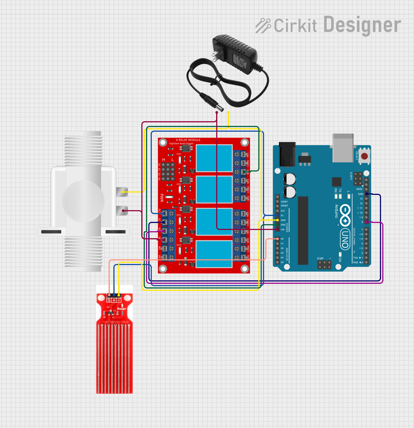
Circuit Documentation
Summary
This circuit is designed to monitor water levels using a water sensor and control a solenoid valve through a relay module. The system is powered by a 12V power supply and an Arduino UNO microcontroller, which reads the sensor data and actuates the relay based on the water level.
Component List
12V Power Supply
- Description: Provides 12V DC power to the circuit.
- Pins: +, -
Water Sensor
- Description: Detects the presence of water and outputs a signal proportional to the water level.
- Pins: Signal, VCC, GND
4 Channel Relay Module
- Description: Controls high-power devices like the solenoid valve based on the input signals.
- Pins: N.O. 4, COM 4, N.C. 4, N.O. 3, COM 3, N.C. 3, N.O. 2, COM 2, N.C. 2, N.O. 1, COM 1, N.C. 1, Pin 13, Pin 14, Pin 15, Pin 16, Pin 17, Pin 18, Pin 19, Pin 20, Pin 21, Pin 22, Pin 23, Pin 24, VCC+, VCC- (GND), IN 1, IN 2, IN 3, IN 4
Arduino UNO
- Description: Microcontroller that reads sensor data and controls the relay module.
- Pins: UNUSED, IOREF, Reset, 3.3V, 5V, GND, Vin, A0, A1, A2, A3, A4, A5, SCL, SDA, AREF, D13, D12, D11, D10, D9, D8, D7, D6, D5, D4, D3, D2, D1, D0
Plastic Solenoid Valve
- Description: Controls the flow of water based on the relay module's output.
- Pins: pin1, pin2
Wiring Details
12V Power Supply
+ connected to:
- Plastic Solenoid Valve pin1
- Arduino UNO Vin
- 4 Channel Relay Module IN 2
- connected to:
- Plastic Solenoid Valve pin2
- Arduino UNO GND
- Water Sensor GND
Water Sensor
Signal connected to:
- Arduino UNO A0
VCC connected to:
- Arduino UNO 5V
- 4 Channel Relay Module VCC+
GND connected to:
- 12V Power Supply -
- Plastic Solenoid Valve pin2
- Arduino UNO GND
4 Channel Relay Module
VCC+ connected to:
- Arduino UNO 5V
- Water Sensor VCC
VCC- (GND) connected to:
- Arduino UNO GND
IN 1 connected to:
- Arduino UNO D8
IN 2 connected to:
- 12V Power Supply +
- Plastic Solenoid Valve pin1
- Arduino UNO Vin
N.O. 1 connected to:
- Arduino UNO GND
Arduino UNO
5V connected to:
- 4 Channel Relay Module VCC+
- Water Sensor VCC
GND connected to:
- 12V Power Supply -
- Plastic Solenoid Valve pin2
- Water Sensor GND
- 4 Channel Relay Module VCC- (GND)
- 4 Channel Relay Module N.O. 1
Vin connected to:
- 12V Power Supply +
- Plastic Solenoid Valve pin1
- 4 Channel Relay Module IN 2
A0 connected to:
- Water Sensor Signal
D8 connected to:
- 4 Channel Relay Module IN 1
Documented Code
int sensorPin = A0;
int sensorValue = 0;
int val1 = 0;
int relay = 8;

void setup() {
  pinMode(relay, OUTPUT);
  Serial.begin(9600);
}

void loop() {
  sensorValue = analogRead(sensorPin);
  Serial.print(sensorValue);
  Serial.print("\n");
  val1 = map(sensorValue, 0, 1023, 0, 255);
  Serial.print(val1);
  Serial.print("\n");
  if (val1 > 95) {
    digitalWrite(relay, LOW);
  } else {
    digitalWrite(relay, HIGH);
  }
  delay(500);
}
This code reads the water sensor value from analog pin A0, maps the sensor value to a range of 0-255, and controls the relay connected to digital pin 8 based on the mapped value. If the mapped value exceeds 95, the relay is turned off (LOW), otherwise, it is turned on (HIGH). The sensor value and mapped value are also printed to the serial monitor for debugging purposes.