
Circuit Documentation
Summary
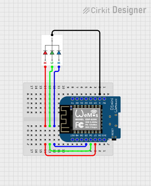
This document provides a detailed overview of a circuit consisting of a Wemos D1 Mini microcontroller and an RGB LED. The Wemos D1 Mini controls the RGB LED by connecting its digital pins to the respective color pins of the LED. The ground pin of the Wemos D1 Mini is connected to the ground pin of the RGB LED.
Component List
RGB LED
- Description: A common cathode RGB LED with four pins: Red (R), Green (G), Blue (B), and Ground (GND).
- Pins: B, G, R, GND
Wemos D1 Mini
- Description: A microcontroller board based on the ESP8266, featuring multiple digital and analog pins.
- Pins: RST, A0, D0, D5, D6, D7, D8, 3V3, 5V, G, D4, D3, D2, D1, RX, TX
Wiring Details
RGB LED
- Pin B: Connected to Wemos D1 Mini D5
- Pin G: Connected to Wemos D1 Mini D6
- Pin R: Connected to Wemos D1 Mini D7
- Pin GND: Connected to Wemos D1 Mini G
Wemos D1 Mini
- Pin D5: Connected to RGB LED B
- Pin D6: Connected to RGB LED G
- Pin D7: Connected to RGB LED R
- Pin G: Connected to RGB LED GND
Code Documentation
sketch.ino
void setup() {
  // put your setup code here, to run once:

}

void loop() {
  // put your main code here, to run repeatedly:

}
documentation.txt
This document provides a comprehensive overview of the circuit, including the components used, their connections, and the code running on the microcontroller.