
Wi-Fi Enabled Gas Leak Detection and Alert System with ESP8266 and SIM800L
View and Edit Project In Cirkit Designer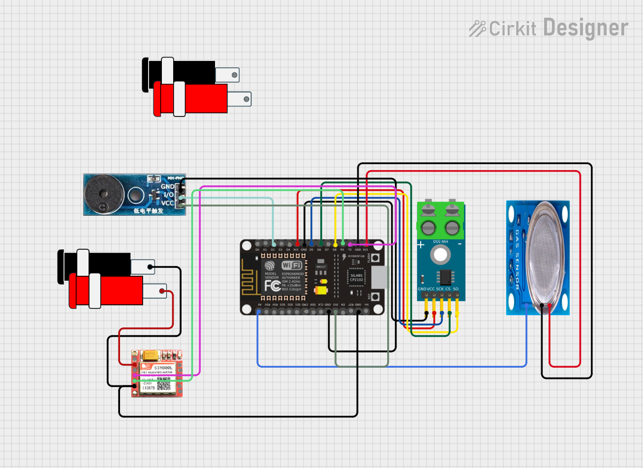
Circuit Documentation
Summary
This document provides a detailed overview of a circuit that includes an ESP8266 NodeMCU, a MAX6675 Module, an MQ-5 gas sensor, a Buzzer Module, a SIM800L GSM module, and two 5V connectors. The circuit is designed to interface these components for various functionalities such as temperature sensing, gas detection, sound alert, and GSM communication.
Component List
ESP8266 NodeMCU
- Description: A low-cost Wi-Fi microcontroller with GPIO, ADC, and UART capabilities.
- Pins: D0, D1, D2, D3, D4, 3V3, GND, D5, D6, D7, D8, RX, TX, A0, RSV, SD3, SD2, SD1, CMD, SD0, CLK, EN, RST, VIN
MAX6675 Module
- Description: A digital thermocouple temperature sensor module.
- Pins: GND, VCC, SCK, CS, SO, -, +
MQ-5 Gas Sensor
- Description: A gas sensor module for detecting LPG, natural gas, and coal gas.
- Pins: VCC, GND, Digi Out, Analog out
Buzzer Module
- Description: A simple buzzer module for sound alerts.
- Pins: GND, Vcc, I/O
SIM800L GSM Module
- Description: A GSM module for sending and receiving SMS and making calls.
- Pins: NFT, RING, VCC, DTR, RST, MIC +, RXD, MIC-, TXD, SPK+, GND, SPK-
Connector 5V
- Description: A 5V power connector.
- Pins: GND, VCC
Wiring Details
ESP8266 NodeMCU
- D2 is connected to I/O of the Buzzer Module.
- 3V3 is connected to VCC of the MAX6675 Module.
- GND is connected to GND of the MAX6675 Module.
- D5 is connected to SCK of the MAX6675 Module.
- D6 is connected to CS of the MAX6675 Module.
- D8 is connected to SO of the MAX6675 Module.
- RX is connected to TXD of the SIM800L GSM Module.
- TX is connected to RXD of the SIM800L GSM Module.
- GND is connected to GND of the MQ-5 Gas Sensor.
- 3V3 is connected to VCC of the MQ-5 Gas Sensor.
- A0 is connected to Analog out of the MQ-5 Gas Sensor.
- GND is connected to GND of the Buzzer Module.
- 3V3 is connected to Vcc of the Buzzer Module.
- GND is connected to GND of the SIM800L GSM Module and GND of the 5V Connector.
- 3V3 is connected to VCC of the SIM800L GSM Module and VCC of the 5V Connector.
MAX6675 Module
- VCC is connected to 3V3 of the ESP8266 NodeMCU.
- GND is connected to GND of the ESP8266 NodeMCU.
- SCK is connected to D5 of the ESP8266 NodeMCU.
- CS is connected to D6 of the ESP8266 NodeMCU.
- SO is connected to D8 of the ESP8266 NodeMCU.
MQ-5 Gas Sensor
- GND is connected to GND of the ESP8266 NodeMCU.
- VCC is connected to 3V3 of the ESP8266 NodeMCU.
- Analog out is connected to A0 of the ESP8266 NodeMCU.
Buzzer Module
- I/O is connected to D2 of the ESP8266 NodeMCU.
- GND is connected to GND of the ESP8266 NodeMCU.
- Vcc is connected to 3V3 of the ESP8266 NodeMCU.
SIM800L GSM Module
- TXD is connected to RX of the ESP8266 NodeMCU.
- RXD is connected to TX of the ESP8266 NodeMCU.
- GND is connected to GND of the ESP8266 NodeMCU and GND of the 5V Connector.
- VCC is connected to VCC of the 5V Connector.
Connector 5V
- GND is connected to GND of the SIM800L GSM Module and GND of the ESP8266 NodeMCU.
- VCC is connected to VCC of the SIM800L GSM Module and 3V3 of the ESP8266 NodeMCU.
Code
No code is provided for this circuit.