
Arduino Mega 2560 Controlled Heater and Stirrer with Resistor Network
View and Edit Project In Cirkit Designer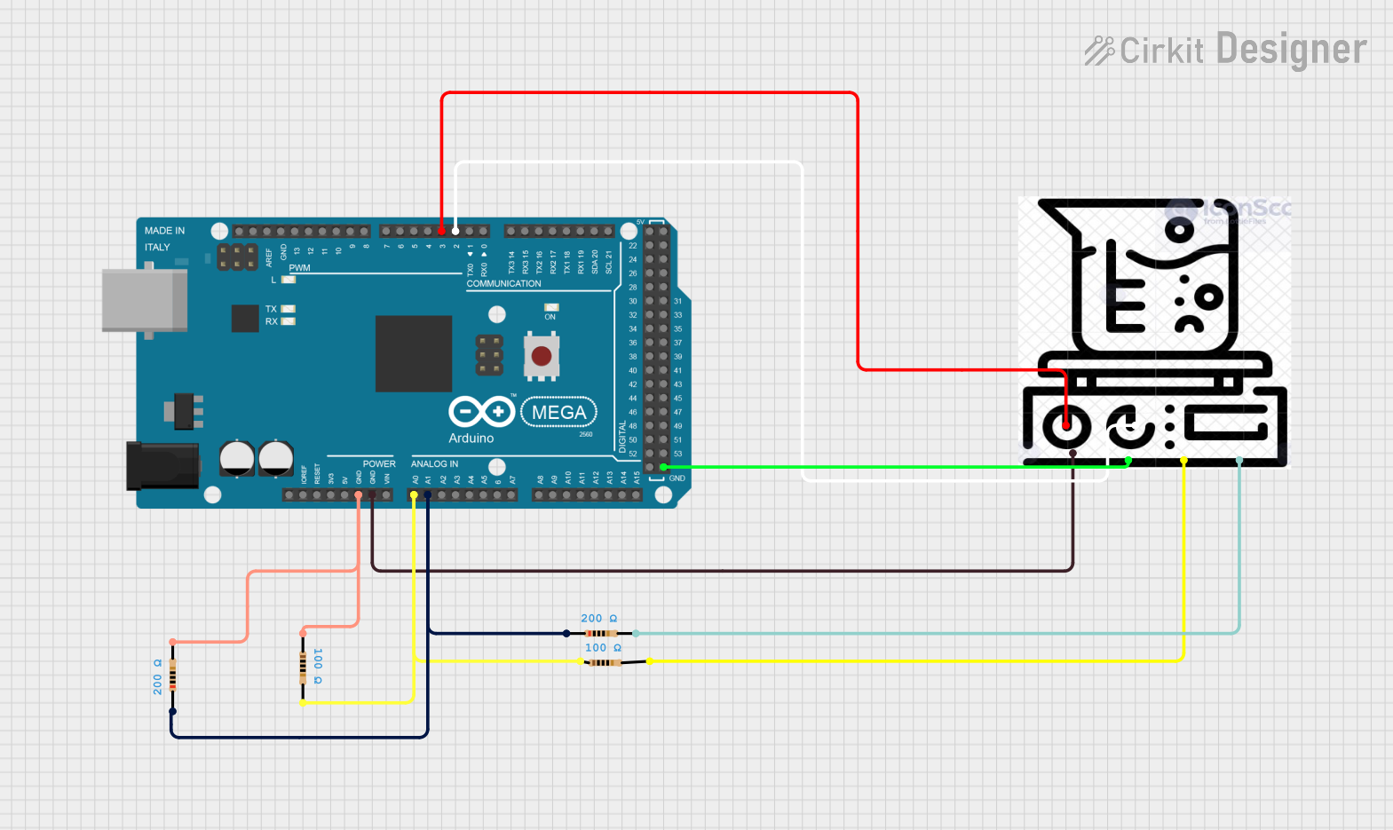
Circuit Documentation
Summary
This document provides a detailed overview of a circuit that includes a heater, an Arduino Mega 2560 microcontroller, and several resistors. The circuit is designed to control the heater and stirrer using the Arduino, with additional resistors for various purposes. The document includes a component list, wiring details, and the embedded code used in the microcontroller.
Component List
Heater
- Description: A heater component with multiple pins for heater, stirrer, ground, and color-coded connections.
- Pins: Heater, Stirrer, GND, Yellow, Blue
Arduino Mega 2560
- Description: A microcontroller board based on the ATmega2560, used for controlling various components in the circuit.
- Pins: IOREF, RESET, 3V3, 5V, GND, VIN, A0-A15, D0-D53, AREF, SDA, SCL
Resistor 1
- Description: A resistor with a resistance of 100 Ohms.
- Pins: pin1, pin2
- Properties: Resistance: 100 Ohms
Resistor 2
- Description: A resistor with a resistance of 100 Ohms.
- Pins: pin1, pin2
- Properties: Resistance: 100 Ohms
Resistor 3
- Description: A resistor with a resistance of 200 Ohms.
- Pins: pin1, pin2
- Properties: Resistance: 200 Ohms
Resistor 4
- Description: A resistor with a resistance of 200 Ohms.
- Pins: pin1, pin2
- Properties: Resistance: 200 Ohms
Wiring Details
Heater
- Heater Pin: Connected to Arduino Mega 2560 D3 PWM pin.
- Stirrer Pin: Connected to Arduino Mega 2560 D2 PWM pin.
- GND Pin: Connected to Arduino Mega 2560 GND pin.
- Yellow Pin: Connected to Resistor 1 pin2.
- Blue Pin: Connected to Resistor 4 pin2.
Arduino Mega 2560
- D3 PWM Pin: Connected to Heater Heater pin.
- D2 PWM Pin: Connected to Heater Stirrer pin.
- GND Pin: Connected to Heater GND pin, Resistor 3 pin2, and Resistor 2 pin1.
- A0 Pin: Connected to Resistor 1 pin1 and Resistor 2 pin2.
- A1 Pin: Connected to Resistor 3 pin1 and Resistor 4 pin1.
Resistor 1
- pin1: Connected to Arduino Mega 2560 A0 pin.
- pin2: Connected to Heater Yellow pin.
Resistor 2
- pin1: Connected to Arduino Mega 2560 GND pin.
- pin2: Connected to Arduino Mega 2560 A0 pin.
Resistor 3
- pin1: Connected to Arduino Mega 2560 A1 pin.
- pin2: Connected to Arduino Mega 2560 GND pin.
Resistor 4
- pin1: Connected to Arduino Mega 2560 A1 pin.
- pin2: Connected to Heater Blue pin.
Embedded Code
Arduino Mega 2560 Code
File Name: sketch.ino
void setup() {
  // put your setup code here, to run once:

}

void loop() {
  // put your main code here, to run repeatedly:

}
File Name: documentation.txt
This concludes the documentation for the circuit. The provided information includes a summary, detailed component list, wiring details, and the embedded code used in the Arduino Mega 2560 microcontroller.