Cirkit Designer
Your all-in-one circuit design IDE
Home /
Project Documentation
ESP8266 Wi-Fi Enabled Battery-Powered Voltage Monitoring System with LCD Display and Buzzer Alert
Circuit Documentation
Summary
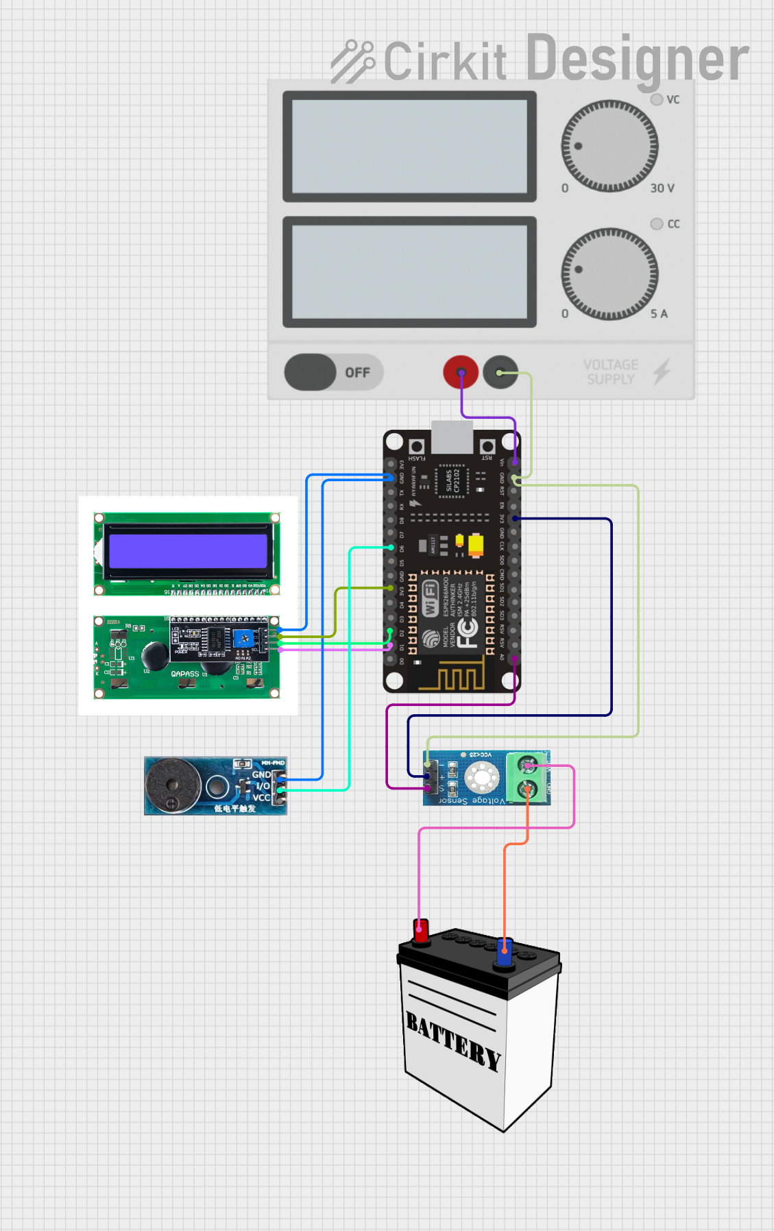
This document provides a detailed overview of a circuit that includes a power supply, a 12V battery, an ESP8266 NodeMCU microcontroller, an LCD I2C module, a buzzer module, and a voltage sensor. The circuit is designed to monitor voltage levels and display them on an LCD, with an alert mechanism using a buzzer.
Component List
Power Supply
- Pins: +, -
- Description: Provides power to the circuit.
12V Battery
- Pins: VCC, GND
- Description: Supplies 12V power to the voltage sensor.
ESP8266 NodeMCU
- Pins: D0, D1, D2, D3, D4, 3V3, GND, D5, D6, D7, D8, RX, TX, A0, RSV, SD3, SD2, SD1, CMD, SD0, CLK, EN, RST, VIN
- Description: Microcontroller used for processing and control.
LCD I2C Module
- Pins: GND, VCC, SDA, SCL
- Description: Displays voltage readings.
Buzzer Module
- Pins: GND, Vcc, I/O
- Description: Provides audible alerts.
Voltage Sensor DC 25V
- Pins: +, -, output, gnd, vcc
- Description: Measures voltage levels.
Wiring Details
Power Supply
- + connected to VIN of ESP8266 NodeMCU
- - connected to GND of ESP8266 NodeMCU and - of Voltage Sensor DC 25V
12V Battery
- VCC connected to vcc of Voltage Sensor DC 25V
- GND connected to gnd of Voltage Sensor DC 25V
ESP8266 NodeMCU
- VIN connected to + of Power Supply
- GND connected to - of Power Supply and GND of Buzzer Module and GND of LCD I2C Module
- D1 connected to SCL of LCD I2C Module
- D2 connected to SDA of LCD I2C Module
- 3V3 connected to VCC of LCD I2C Module and + of Voltage Sensor DC 25V
- D6 connected to I/O of Buzzer Module
- A0 connected to output of Voltage Sensor DC 25V
LCD I2C Module
- GND connected to GND of ESP8266 NodeMCU
- VCC connected to 3V3 of ESP8266 NodeMCU
- SDA connected to D2 of ESP8266 NodeMCU
- SCL connected to D1 of ESP8266 NodeMCU
Buzzer Module
- GND connected to GND of ESP8266 NodeMCU
- Vcc not connected
- I/O connected to D6 of ESP8266 NodeMCU
Voltage Sensor DC 25V
- + connected to 3V3 of ESP8266 NodeMCU
- - connected to GND of ESP8266 NodeMCU and - of Power Supply
- output connected to A0 of ESP8266 NodeMCU
- gnd connected to GND of 12V Battery
- vcc connected to VCC of 12V Battery
Code
No code is provided for this circuit.
This document provides a comprehensive overview of the circuit, including a summary, component list, wiring details, and code documentation. The wiring details ensure that each component is correctly connected to achieve the desired functionality.