
Arduino UNO with MAX30102 Pulse Oximeter and I2C LCD Display
View and Edit Project In Cirkit Designer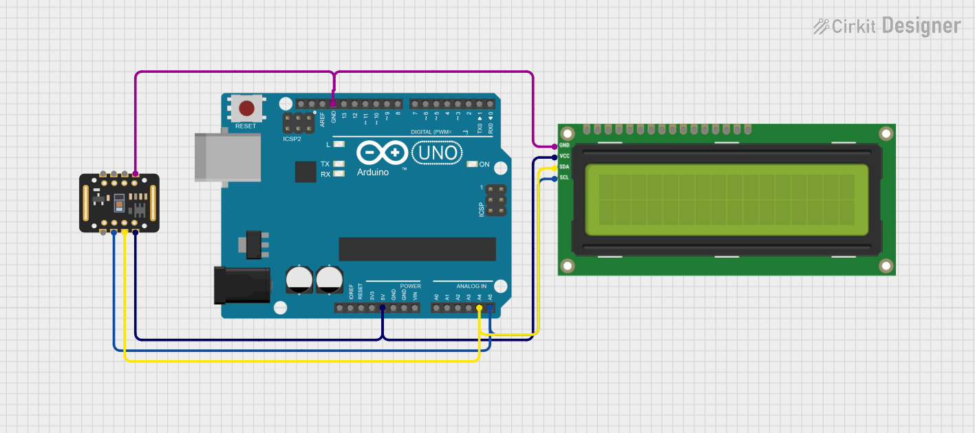
Circuit Documentation
Summary
The circuit in question is designed to interface a MAX30102 sensor with an Arduino UNO microcontroller and display data on an I2C LCD 16x2 screen. The MAX30102 is a high-sensitivity pulse oximeter and heart-rate sensor that communicates with the Arduino UNO via I2C protocol. The Arduino UNO processes the data from the MAX30102 and outputs the information to the LCD screen, which also uses I2C for communication. The circuit is powered by the 5V output from the Arduino UNO, which is distributed to both the MAX30102 sensor and the LCD screen.
Component List
MAX30102 Sensor
- Description: A high-sensitivity pulse oximeter and heart-rate sensor.
- Pins: VIN, SDA, SCL, GND, RD, IRD, INT
Arduino UNO
- Description: A microcontroller board based on the ATmega328P.
- Pins: UNUSED, IOREF, Reset, 3.3V, 5V, GND, Vin, A0-A5, SCL, SDA, AREF, D0-D13
I2C LCD 16x2 Screen
- Description: A 16x2 character LCD display with an I2C interface.
- Pins: SCL, SDA, VCC (5V), GND, VDD, VO, RS, RW, E, D0-D7, BLA, BLK
Wiring Details
MAX30102 Sensor
- VIN: Connected to 5V from the Arduino UNO.
- SDA: Connected to SDA (A4) on the Arduino UNO.
- SCL: Connected to SCL (A5) on the Arduino UNO.
- GND: Connected to GND on the Arduino UNO.
Arduino UNO
- 5V: Provides power to the MAX30102 sensor and the I2C LCD screen.
- GND: Common ground for the circuit.
- A4 (SDA): I2C data line connected to SDA on MAX30102 and LCD screen.
- A5 (SCL): I2C clock line connected to SCL on MAX30102 and LCD screen.
I2C LCD 16x2 Screen
- VCC (5V): Connected to 5V from the Arduino UNO.
- SDA: Connected to SDA (A4) on the Arduino UNO.
- SCL: Connected to SCL (A5) on the Arduino UNO.
- GND: Connected to GND on the Arduino UNO.
Documented Code
#include <Wire.h>
#include <Adafruit_Sensor.h>
#include "Adafruit_MAX30105.h"
#include <LiquidCrystal_I2C.h>

Adafruit_MAX30105 max30102;
LiquidCrystal_I2C lcd(0x27, 16, 2);  // Change 0x27 to your LCD I2C address

void setup() {
  lcd.begin();
  lcd.backlight();

  Serial.begin(115200);

  if (!max30102.begin()) {
    Serial.println("Could not find a valid MAX30102 sensor, check wiring!");
    while (1);
  }

  // Initialize sensor
  max30102.setup();

  // Check if LCD is initialized properly
  if (!lcd) {
    Serial.println("LCD initialization failed, check wiring!");
    while (1);
  }
}

void loop() {
  // Generate random values for heartbeat and SpO2 for testing
  int heartbeat = random(60, 100);  // Random heartbeat between 60 and 100 BPM
  int spo2 = random(90, 100);       // Random SpO2 level between 90% and 100%

  lcd.clear();

  lcd.setCursor(0, 0);
  lcd.print("HB: ");
  lcd.print(heartbeat);
  lcd.print(" BPM");

  lcd.setCursor(0, 1);
  lcd.print("SpO2: ");
  lcd.print(spo2);
  lcd.print(" %");

  delay(1000);
}
Code Explanation
- The code begins by including the necessary libraries for I2C communication, sensor, and LCD interfacing.
- The
max30102object is created to interact with the MAX30102 sensor, and thelcdobject is created for the LCD screen. - In the
setup()function, the LCD is initialized and the backlight is turned on. The serial communication is started for debugging purposes. - The MAX30102 sensor is initialized, and if it fails, the program enters an infinite loop, effectively halting the system.
- The
loop()function generates random values for heartbeat and SpO2 to simulate sensor data. This data is then displayed on the LCD screen. - The
delay(1000)call pauses the loop for one second before updating the display with new data.