
Arduino UNO Based Environmental Monitoring System with SMS Alerts
View and Edit Project In Cirkit Designer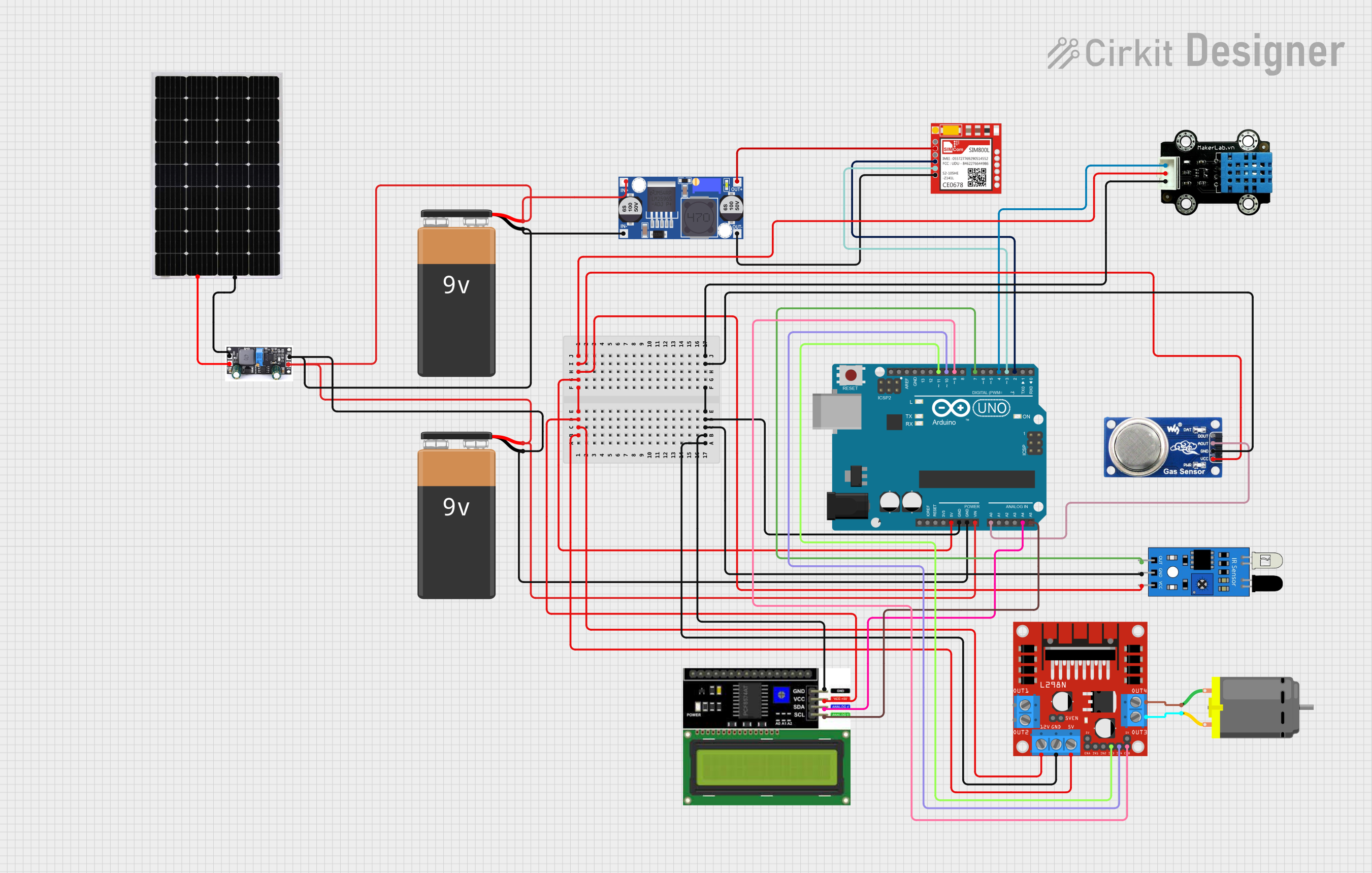
Circuit Documentation
Summary
The circuit is designed to monitor environmental parameters such as temperature, humidity, smoke levels, and detect obstructions using an IR sensor. It includes a microcontroller (Arduino UNO) that interfaces with a DHT11 temperature and humidity sensor, an MQ6 gas sensor, an IR sensor, and an LCD I2C display for output. The system can control a DC motor via an L298N motor driver and has the capability to send SMS alerts using a SIM800L GSM module. Power is supplied by 9V batteries, regulated by a buck converter, and supplemented by a solar panel with a charge controller. The Arduino UNO also manages the motor's operation based on temperature readings and sends alerts when predefined thresholds are exceeded.
Component List
- 9V Battery: Provides power to the circuit.
- Sim800l: GSM module used for sending SMS alerts.
- MKE-S14 DHT11 Temperature And Humidity Sensor: Measures temperature and humidity levels.
- MQ6: Gas sensor for detecting LPG, butane, propane, methane, alcohol, hydrogen, and smoke.
- IR Sensor: Detects obstructions in the path of the IR signal.
- LCD I2C Display: Displays temperature, humidity, smoke levels, and IR sensor status.
- L298N DC Motor Driver: Controls the operation of a DC motor.
- DC Motor: Actuator controlled by the L298N motor driver.
- Buck Converter: Steps down voltage from the 9V battery to a lower voltage suitable for the Sim800l module.
- Arduino UNO: Microcontroller that serves as the brain of the circuit, interfacing with sensors, the display, and the GSM module.
- Solar Panel: Provides supplementary power to charge the battery.
- Charge Controller: Manages the charging of the battery from the solar panel.
Wiring Details
9V Battery
- Provides power to the circuit.
Sim800l
- NET: Not connected in this circuit.
- RST: Not connected in this circuit.
- VCC: Connected to the output of the Buck Converter.
- RXD: Connected to pin D2 of the Arduino UNO.
- TXD: Connected to pin D3 of the Arduino UNO.
- GND: Connected to the output of the Buck Converter.
MKE-S14 DHT11 Temperature And Humidity Sensor
- SIG: Connected to pin D4 of the Arduino UNO.
- 5V: Connected to the 5V output of the Arduino UNO.
- GND: Connected to the GND of the Arduino UNO.
MQ6
- VCC: Connected to the 5V output of the Arduino UNO.
- GND: Connected to the GND of the Arduino UNO.
- A0: Connected to pin A0 of the Arduino UNO.
- DO: Not connected in this circuit.
IR Sensor
- Out: Connected to pin D7 of the Arduino UNO.
- Gnd: Connected to the GND of the Arduino UNO.
- Vcc: Connected to the 5V output of the Arduino UNO.
LCD I2C Display
- GND: Connected to the GND of the Arduino UNO.
- VCC: Connected to the 5V output of the Arduino UNO.
- SDA: Connected to pin A4 of the Arduino UNO.
- SCL: Connected to pin A5 of the Arduino UNO.
L298N DC Motor Driver
- OUT1, OUT2: Not connected in this circuit.
- 12V: Connected to the 12V output of the Arduino UNO.
- GND: Connected to the GND of the Arduino UNO.
- 5V: Connected to the 5V output of the Arduino UNO.
- OUT3, OUT4: Connected to the DC Motor.
- 5V-ENA-JMP-I, 5V-ENA-JMP-O, +5V-J1, +5V-J2: Not connected in this circuit.
- ENA: Connected to pin D9 of the Arduino UNO.
- IN1: Connected to pin D10 of the Arduino UNO.
- IN2: Connected to pin D11 of the Arduino UNO.
- IN3, IN4, ENB: Not connected in this circuit.
DC Motor
- Pin 1: Connected to OUT4 of the L298N motor driver.
- Pin 2: Connected to OUT3 of the L298N motor driver.
Buck Converter
- IN+: Connected to the positive terminal of the 9V Battery.
- IN-: Connected to the negative terminal of the 9V Battery.
- OUT+: Connected to the VCC of the Sim800l.
- OUT-: Connected to the GND of the Sim800l.
Arduino UNO
- 5V: Provides power to various sensors and the LCD display.
- GND: Common ground for the circuit.
- Vin: Connected to the positive terminal of the 9V Battery.
- A0-A5: Analog pins used for sensor data and I2C communication.
- D0-D13: Digital pins used for controlling and interfacing with various components.
Solar Panel
- +: Connected to the BAT pin of the Charge Controller.
- -: Connected to the GND pin of the Charge Controller.
Charge Controller
- GND: Connected to the negative terminal of the 9V Battery.
- BAT: Connected to the positive terminal of the 9V Battery.
- Vin: Connected to the positive terminal of the Solar Panel.
Documented Code
#include <DHT.h>
#include <SoftwareSerial.h>
#include <Wire.h>
#include <LiquidCrystal_I2C.h>

// Pin Definitions
#define DHTPIN 4             // DHT11 Data pin connected to Arduino pin 4
#define DHTTYPE DHT11        // Define the type of DHT sensor
#define SIM800_RX 3          // SIM800L RX pin connected to pin 3
#define SIM800_TX 2          // SIM800L TX pin connected to pin 2
#define MQ2_PIN A0           // MQ2 Smoke Sensor analog pin connected to A0
#define IR_SENSOR_PIN 7      // IR Sensor digital pin connected to pin 7
#define LED_PIN 13           // LED pin connected to pin 13

// L298N Motor Driver Pin Definitions
#define ENA 9                // Enable pin for motor A (connected to a PWM pin on Arduino)
#define IN1 10               // Control pin 1 for motor A
#define IN2 11               // Control pin 2 for motor A

// Constants
#define PREDETERMINED_TEMP 28  // Predetermined temperature value in °C
#define SMOKE_THRESHOLD 20     // Predefined smoke level threshold

#define PHONE_NUMBER_1 "+447909488634" // First phone number
#define PHONE_NUMBER_2 "+447909488634" // Second phone number (changed for clarity)

// Create instances
SoftwareSerial mySerial(SIM800_RX, SIM800_TX);
DHT dht(DHTPIN, DHTTYPE);
LiquidCrystal_I2C lcd(0x21, 16, 2); // Initialize the LCD with I2C address 0x27 and size 16x2

// Flags to track if messages have been sent for temperature, smoke, and obstruction
bool messageSentTemp1 = false;
bool messageSentTemp2 = false;
bool messageSentSmoke1 = false;
bool messageSentSmoke2 = false;
bool messageSentObstruction = false;

// Motor state
bool motorRunning = false;

// Variables for LED blinking detection
unsigned long lastBlinkCheck = 0;
const unsigned long blinkInterval = 3000; // 3 seconds
bool connectionEstablished = false;

void setup() {
  Serial.begin(9600); // Start the Serial Monitor
  mySerial.begin(9600); // Start Software Serial for SIM800L

  dht.begin(); // Initialize DHT sensor
  pinMode(IR_SENSOR_PIN, INPUT); // Set IR sensor pin as input
  pinMode(LED_PIN, OUTPUT); // Set LED pin as output

  // Initialize L298N Motor Driver pins
  pinMode(ENA, OUTPUT);
  pinMode(IN1, OUTPUT);
  pinMode(IN2, OUTPUT);

  // Initialize I2C LCD
  lcd.init();
  lcd.backlight();
  lcd.print("UP2165711...");

  Serial.println("Initializing...");
  delay(1000);

  // Initialize the SIM800L module
  sendATCommand("AT"); // Test communication
  sendATCommand("AT+CMGF=1"); // Set SMS mode to text
  sendATCommand("AT+CSMP=17,167,0,0"); // Set SMS text mode
}

void loop() {
  unsigned long currentMillis = millis();

  // Check SIM800L network registration status
  checkNetworkStatus();

  // Check if 3 seconds have passed to update connection status
  if (currentMillis - lastBlinkCheck >= blinkInterval) {
    if (connectionEstablished) {
      lcd.clear();
      lcd.setCursor(0, 0);
      lcd.print("Connection");
      lcd.setCursor(0, 1);
      lcd.print("Established");
    }
    lastBlinkCheck = currentMillis