
Arduino UNO-Based Smart Street Light Control with LDR and PIR Sensors
View and Edit Project In Cirkit Designer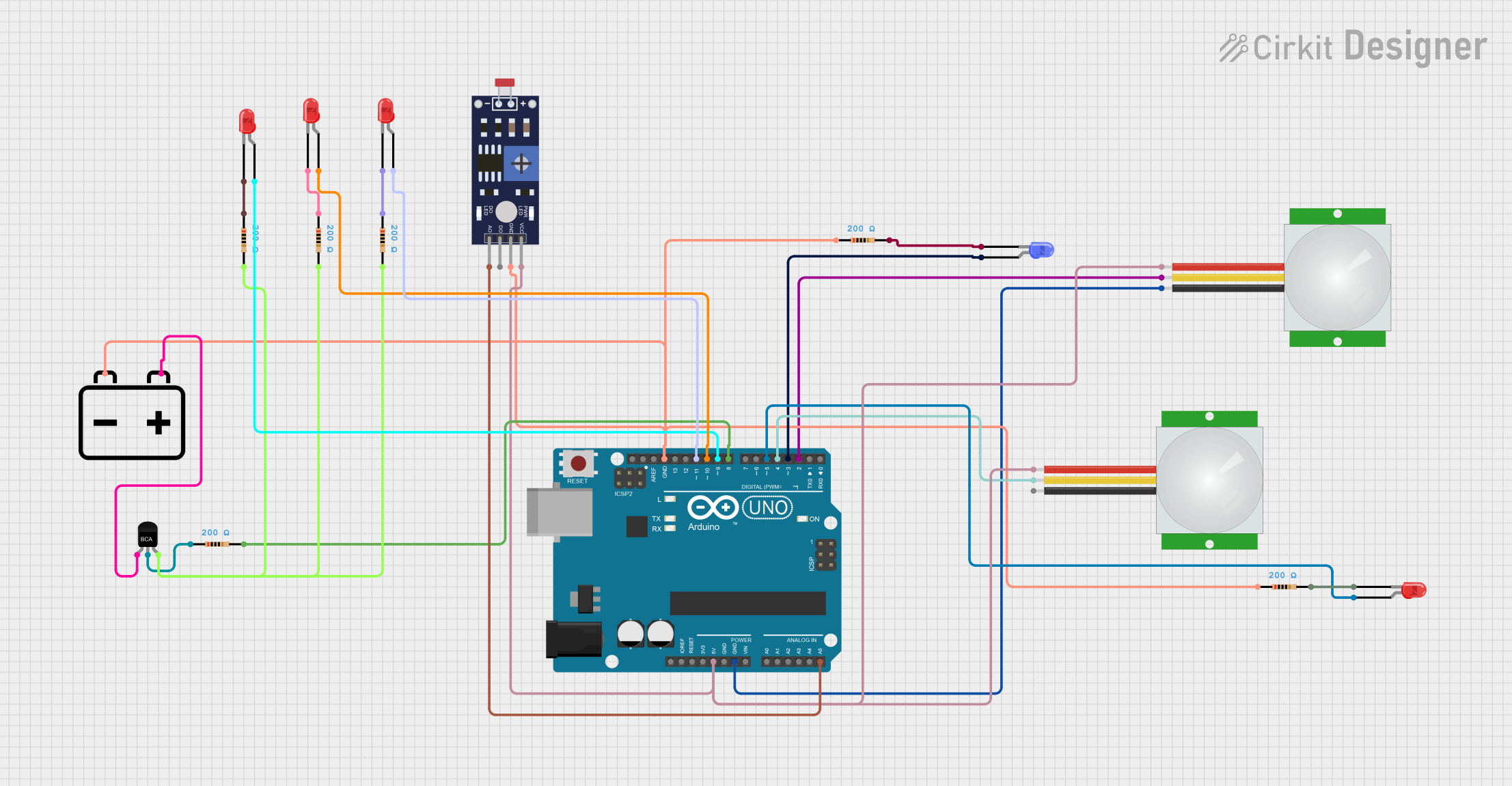
Street Light Control Project Documentation
Summary
This project is a street light control system that uses an Arduino UNO microcontroller to manage street lights based on inputs from a Light Dependent Resistor (LDR) sensor and two Passive Infrared (PIR) sensors. The LDR sensor determines whether it is day or night, and the PIR sensors detect motion. At night, three LEDs are turned on via a transistor switch, and an additional LED is turned on when motion is detected.
Component List
Arduino UNO
- Description: Microcontroller board based on the ATmega328P.
- Pins: UNUSED, IOREF, Reset, 3.3V, 5V, GND, Vin, A0, A1, A2, A3, A4, A5, SCL, SDA, AREF, D13, D12, D11, D10, D9, D8, D7, D6, D5, D4, D3, D2, D1, D0
PIR Sensor
- Description: Passive Infrared sensor for motion detection.
- Pins: VDD, SIG, GND
LED: Two Pin (red)
- Description: Red LED with two pins.
- Pins: cathode, anode
LED: Two Pin (blue)
- Description: Blue LED with two pins.
- Pins: cathode, anode
Resistor
- Description: Resistor with a resistance of 200 Ohms.
- Pins: pin1, pin2
12v Battery
- Description: Power source for the circuit.
- Pins: -, +
NPN-Transistor
- Description: NPN transistor for switching.
- Pins: E, C, B
Photoresistor (LDR) Sensor (Wokwi Compatible)
- Description: Light Dependent Resistor sensor for detecting light levels.
- Pins: VCC, GND, DO, AO
Wiring Details
Arduino UNO
5V connected to:
- VDD of PIR sensor
- VDD of PIR sensor
- VCC of Photoresistor (LDR) Sensor
GND connected to:
- GND of PIR sensor
- GND of Photoresistor (LDR) Sensor
- pin1 of Resistor
- pin1 of Resistor
A5 connected to:
- AO of Photoresistor (LDR) Sensor
D11 connected to:
- anode of LED (red)
D10 connected to:
- anode of LED (red)
D9 connected to:
- anode of LED (red)
D8 connected to:
- pin2 of Resistor
D5 connected to:
- anode of LED (red)
D4 connected to:
- SIG of PIR sensor
D3 connected to:
- anode of LED (blue)
D2 connected to:
- SIG of PIR sensor
PIR Sensor
VDD connected to:
- 5V of Arduino UNO
GND connected to:
- GND of Arduino UNO
SIG connected to:
- D2 of Arduino UNO
- D4 of Arduino UNO
LED: Two Pin (red)
anode connected to:
- D11 of Arduino UNO
- D10 of Arduino UNO
- D9 of Arduino UNO
- D5 of Arduino UNO
cathode connected to:
- pin2 of Resistor
- pin2 of Resistor
- pin2 of Resistor
- pin2 of Resistor
LED: Two Pin (blue)
anode connected to:
- D3 of Arduino UNO
cathode connected to:
- pin2 of Resistor
Resistor
pin1 connected to:
- GND of Arduino UNO
- GND of Arduino UNO
- GND of Arduino UNO
- GND of Arduino UNO
- C of NPN-Transistor
pin2 connected to:
- cathode of LED (red)
- cathode of LED (red)
- cathode of LED (red)
- cathode of LED (red)
- pin2 of Resistor
- pin2 of Resistor
- B of NPN-Transistor
12v Battery
- connected to:
- pin1 of Resistor
- pin1 of Resistor
+ connected to:
- E of NPN-Transistor
NPN-Transistor
E connected to:
-
- of 12v Battery
-
C connected to:
- pin1 of Resistor
B connected to:
- pin2 of Resistor
Photoresistor (LDR) Sensor (Wokwi Compatible)
VCC connected to:
- 5V of Arduino UNO
GND connected to:
- GND of Arduino UNO
AO connected to:
- A5 of Arduino UNO
Code Documentation
/*
 * Street Light Control Project
 * This code controls street lights based on LDR and PIR sensors.
 * - LDR sensor determines day/night.
 * - At night, three LEDs are turned on via a transistor switch.
 * - PIR sensor detects motion to turn on an additional LED.
 */

const int ldrPin = A5; // LDR sensor pin
const int pirPin1 = 2; // PIR sensor 1 pin
const int pirPin2 = 4; // PIR sensor 2 pin
const int ledPin1 = 8; // LED controlled by transistor
const int ledPin2 = 9; // LED controlled by transistor
const int ledPin3 = 10; // LED controlled by transistor
const int motionLedPin = 3; // LED for motion detection

void setup() {
  pinMode(ldrPin, INPUT);
  pinMode(pirPin1, INPUT);
  pinMode(pirPin2, INPUT);
  pinMode(ledPin1, OUTPUT);
  pinMode(ledPin2, OUTPUT);
  pinMode(ledPin3, OUTPUT);
  pinMode(motionLedPin, OUTPUT);
  digitalWrite(ledPin1, LOW);
  digitalWrite(ledPin2, LOW);
  digitalWrite(ledPin3, LOW);
  digitalWrite(motionLedPin, LOW);
}

void loop() {
  int ldrValue = analogRead(ldrPin);
  int pirValue1 = digitalRead(pirPin1);
  int pirValue2 = digitalRead(pirPin2);

  // Check if it is night time
  if (ldrValue < 500) { // Adjust threshold as needed
    digitalWrite(ledPin1, HIGH);
    digitalWrite(ledPin2, HIGH);
    digitalWrite(ledPin3, HIGH);
  } else {
    digitalWrite(ledPin1, LOW);
    digitalWrite(ledPin2, LOW);
    digitalWrite(ledPin3, LOW);
  }

  // Check for motion detection
  if (pirValue1 == HIGH || pirValue2 == HIGH) {
    digitalWrite(motionLedPin, HIGH);
  } else {
    digitalWrite(motionLedPin, LOW);
  }

  delay(100); // Small delay to debounce sensors
}
This code initializes the pins for the LDR sensor, PIR sensors, and LEDs. In the loop function, it reads the values from the LDR and PIR sensors. If the LDR value indicates night time, it turns on three LEDs. If either PIR sensor detects motion, it turns on an additional LED. The code includes a small delay to debounce the sensors.