Arduino UNO Controlled Weighing Scale with LCD Display and Keypad Input
Circuit Documentation
Summary
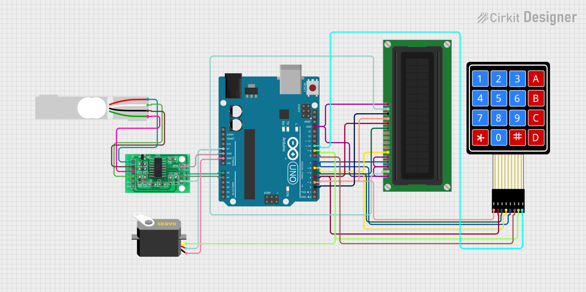
This circuit integrates various components controlled by an Arduino UNO microcontroller to perform a range of functions. The circuit includes a load cell interfaced with an HX711 bridge sensor interface for weight measurement, an LCD display for user interface, a servo motor for actuation, and a 4x4 membrane matrix keypad for user input. The Arduino UNO serves as the central processing unit, managing data acquisition from the load cell, user input from the keypad, and output to the LCD display and servo motor.
Component List
Arduino UNO
- Microcontroller board based on the ATmega328P
- Provides digital and analog I/O pins
- Powers the circuit and controls other components
Load Cell - Red/white/black/green
- Transducer that converts force into an electrical signal
- Used for weight measurement
HX711 - Bridge Sensor Interface
- Precision 24-bit analog-to-digital converter (ADC) for weigh scales
- Interfaces with the load cell to provide digital data to the Arduino
LCD Display (16 pin)
- Alphanumeric liquid crystal display
- Used for displaying information to the user
Servo
- Rotary actuator or linear actuator that allows for precise control of angular or linear position
- Used for controlled movements or to position something
4X4 Membrane Matrix Keypad
- Input device with 16 buttons arranged in a 4x4 grid
- Allows the user to input commands into the system
Wiring Details
Arduino UNO
5Vpin provides power to the HX711, Servo, and LCD DisplayGNDpin is connected to the ground of HX711, Servo, and LCD DisplayA0pin is connected to theDATA (OUT)pin of HX711A1pin is connected to theSCK - CLOCK (IN)pin of HX711- Digital pins
D2toD10are used for interfacing with the LCD Display and the 4x4 Keypad
Load Cell - Red/white/black/green
E+andE-pins are connected to the correspondingE+andE-pins of HX711A-andA+pins are connected to the correspondingA+andA-pins of HX711
HX711 - Bridge Sensor Interface
3.3/3.5V Supplypin is connected to the5Vpin of Arduino UNOGND - GROUNDpin is connected to theGNDpin of Arduino UNODATA (OUT)pin is connected to theA0pin of Arduino UNOSCK - CLOCK (IN)pin is connected to theA1pin of Arduino UNO
LCD Display (16 pin)
VDDandApins are connected to the5Vpin of Arduino UNOVSS,K,VO, andR_Wpins are connected to theGNDpin of Arduino UNORS,E,DB4toDB7pins are connected to digital pinsD7toD2of Arduino UNO respectively
Servo
vccpin is connected to the5Vpin of Arduino UNOgndpin is connected to theGNDpin of Arduino UNOpulsepin is connected to theD9pin of Arduino UNO
4X4 Membrane Matrix Keypad
C1toC4pins are connected to digital pinsD7toD10of Arduino UNO respectivelyR1toR4pins are connected to digital pinsD3toD6of Arduino UNO respectively
Documented Code
Arduino UNO Code (sketch.ino)
void setup() {
  // put your setup code here, to run once:

}

void loop() {
  // put your main code here, to run repeatedly:

}
This code is a template for the Arduino UNO microcontroller. The setup() function is intended to contain initialization code that runs once at the start, while the loop() function is designed for code that runs continuously, handling tasks such as reading sensor data, updating the display, and responding to user input.
Additional Documentation (documentation.txt)
The additional documentation file is empty and does not contain any code or information.