
Dual TB6600 Stepper Motor Driver with Nema 17 Motors and ESP32 Control
View and Edit Project In Cirkit Designer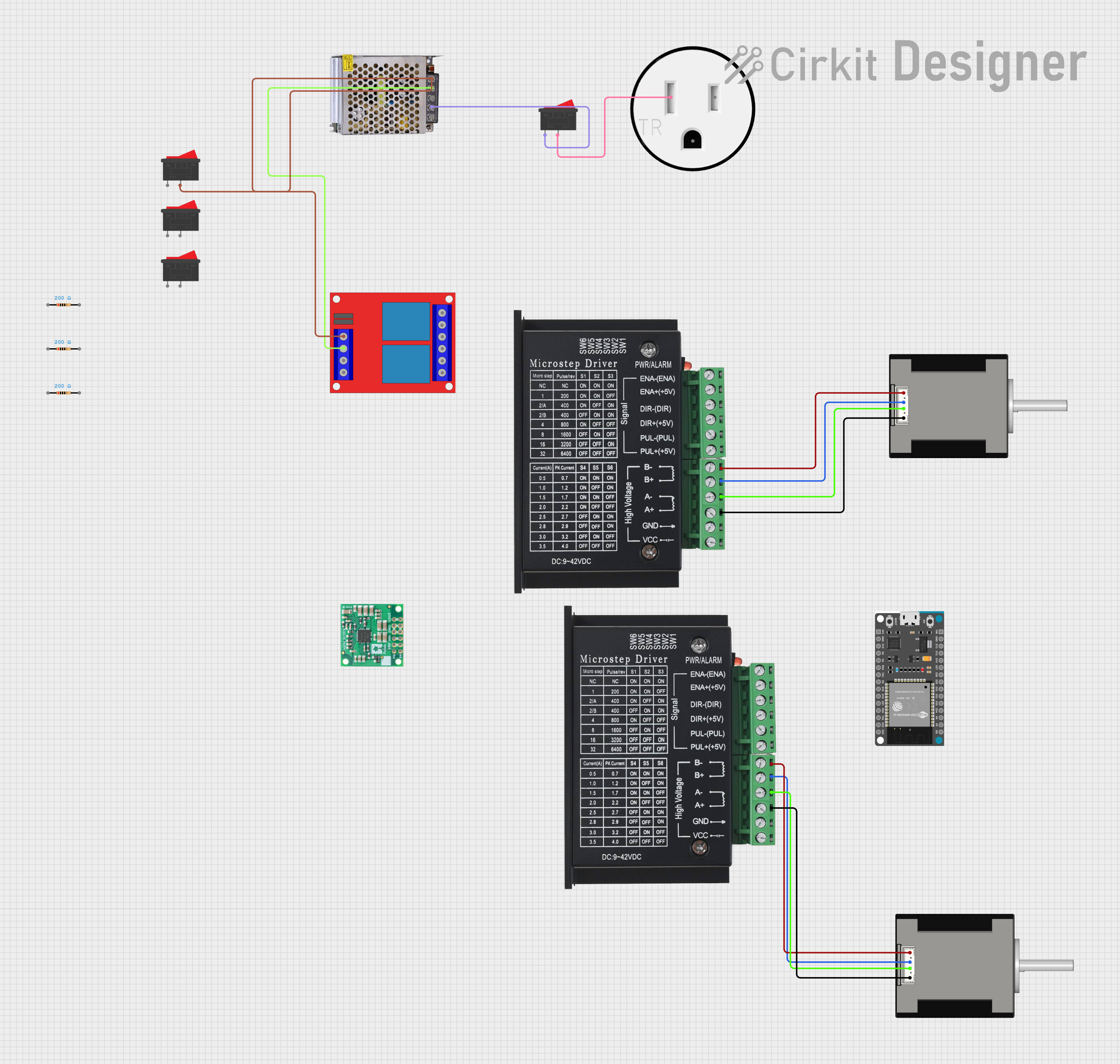
Circuit Documentation
Summary
This document provides a detailed overview of a circuit that includes stepper motor drivers, stepper motors, a voltage regulator, relays, rocker switches, a power supply, and an outlet. The circuit is designed to control stepper motors using TB6600 drivers, powered by a 12V power supply, and includes relays for switching and a voltage regulator for stable 5V output.
Component List
TB6600 Stepper Motor Driver
- Pins: ENA-, ENA+, DIR-, DIR+, PUL-, PUL+, B-, B+, A-, A+, GND, VCC
- Description: Stepper motor driver for controlling Nema 17 stepper motors.
Nema 17 42-STH48 Stepper Motor
- Pins: A2 (black), A1 Green, B2 Red, B1 Blue
- Description: Bipolar stepper motor.
Rocker Switch
- Pins: 1, 2
- Description: Simple on/off switch.
5V, 5.5A Step-Down Voltage Regulator D36V50F5
- Pins: PG, EN, VRP, VIN, GND, VOUT
- Description: Voltage regulator to step down voltage to 5V.
120V Outlet
- Pins: AC Neutral, AC Hot, GND
- Description: Standard 120V AC outlet.
2 Channel 12V Relay
- Pins: 12v +, 12v -, Trigger 1, Trigger 2, NC1, COM1, NO1, NC2, COM2, NO2
- Description: Relay module for switching high-power devices.
Resistor (200 Ohms)
- Pins: pin1, pin2
- Description: Resistor with a resistance of 200 Ohms.
ESP32 Devkit V1
- Pins: 3V3, GND, D15, D2, D4, RX2, TX2, D5, D18, D19, D21, RX0, TX0, D22, D23, EN, VP, VN, D34, D35, D32, D33, D25, D26, D27, D14, D12, D13, VIN
- Description: Microcontroller with Wi-Fi and Bluetooth capabilities.
POWER SUPPLY 12V 5AMP
- Pins: 220V Positive Pole (AC), 220V Negative Pole (AC), GND, GND (DC), 12V-24V Output (DC)
- Description: Power supply providing 12V DC output.
Wiring Details
TB6600 Stepper Motor Driver
TB6600 (Driver 1)
- B- connected to A2 (black) of Nema 17 (Motor 1)
- B+ connected to A1 Green of Nema 17 (Motor 1)
- A- connected to B2 Red of Nema 17 (Motor 1)
- A+ connected to B1 Blue of Nema 17 (Motor 1)
TB6600 (Driver 2)
- B- connected to A2 (black) of Nema 17 (Motor 2)
- B+ connected to A1 Green of Nema 17 (Motor 2)
- A- connected to B2 Red of Nema 17 (Motor 2)
- A+ connected to B1 Blue of Nema 17 (Motor 2)
Nema 17 42-STH48 Stepper Motor
Nema 17 (Motor 1)
- A2 (black) connected to B- of TB6600 (Driver 1)
- A1 Green connected to B+ of TB6600 (Driver 1)
- B2 Red connected to A- of TB6600 (Driver 1)
- B1 Blue connected to A+ of TB6600 (Driver 1)
Nema 17 (Motor 2)
- A2 (black) connected to B- of TB6600 (Driver 2)
- A1 Green connected to B+ of TB6600 (Driver 2)
- B2 Red connected to A- of TB6600 (Driver 2)
- B1 Blue connected to A+ of TB6600 (Driver 2)
Rocker Switch
Rocker Switch 1
- Pin 1 connected to 220V Negative Pole (AC) of POWER SUPPLY 12V 5AMP
- Pin 2 connected to AC Neutral of 120V Outlet
Rocker Switch 2
- Pin 2 connected to 12V-24V Output (DC) of POWER SUPPLY 12V 5AMP and 12v + of 2 Channel 12V Relay
5V, 5.5A Step-Down Voltage Regulator D36V50F5
- No specific connections provided in the net list.
120V Outlet
- AC Neutral connected to Pin 2 of Rocker Switch 1
2 Channel 12V Relay
- 12v + connected to 12V-24V Output (DC) of POWER SUPPLY 12V 5AMP and Pin 2 of Rocker Switch 2
- 12v - connected to GND (DC) of POWER SUPPLY 12V 5AMP
Resistor (200 Ohms)
- No specific connections provided in the net list.
ESP32 Devkit V1
- No specific connections provided in the net list.
POWER SUPPLY 12V 5AMP
- 220V Negative Pole (AC) connected to Pin 1 of Rocker Switch 1
- 12V-24V Output (DC) connected to Pin 2 of Rocker Switch 2 and 12v + of 2 Channel 12V Relay
- GND (DC) connected to 12v - of 2 Channel 12V Relay
Code
No code provided for microcontrollers in this circuit.
This document provides a comprehensive overview of the components and their connections within the circuit. For further details or modifications, please refer to the specific datasheets and manuals of each component.