
Arduino UNO Air Quality Monitoring System with MQ135 and I2C LCD Display
View and Edit Project In Cirkit Designer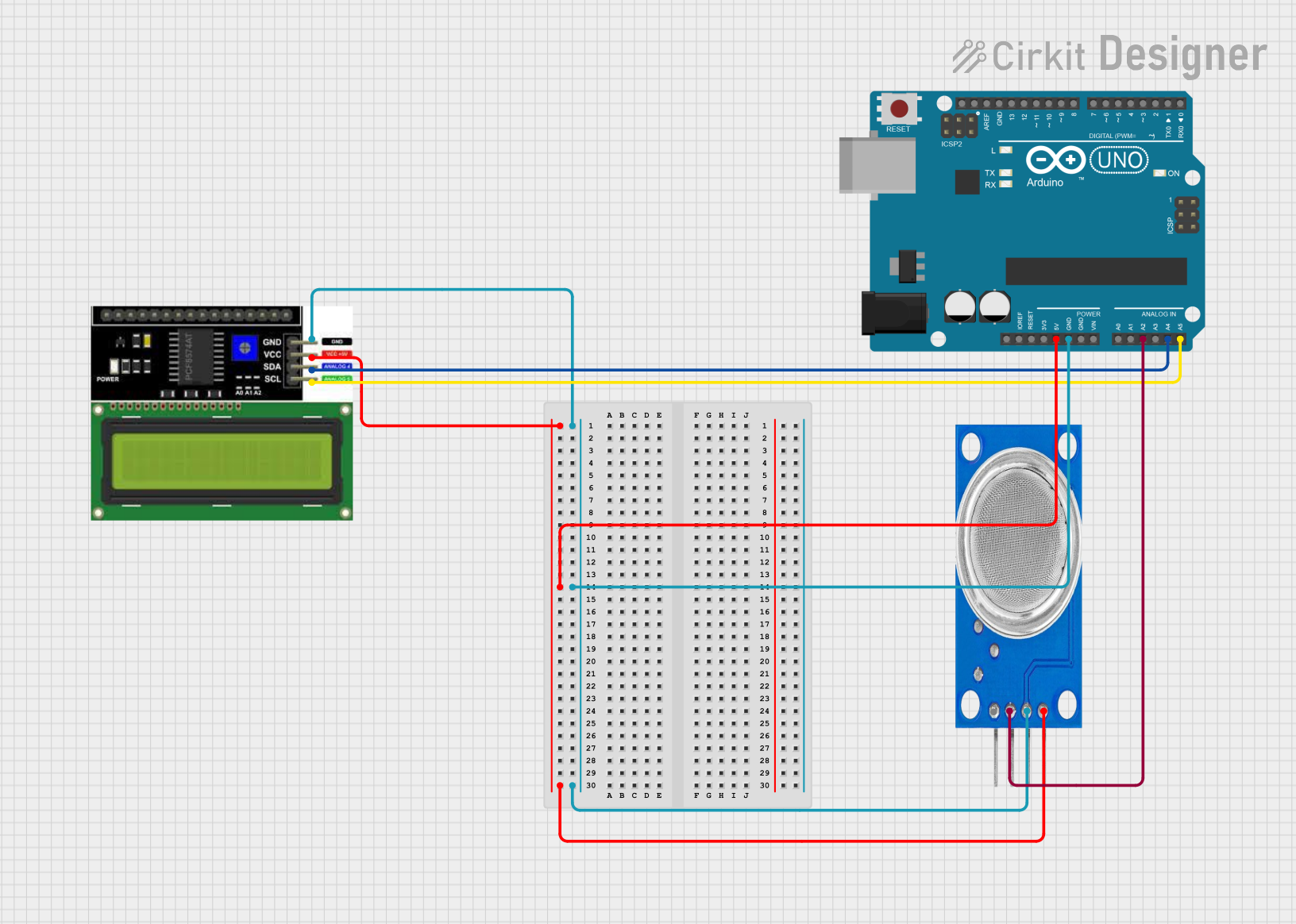
Circuit Documentation
Summary
This circuit is designed to monitor air quality using an MQ135 gas sensor and display the readings on an I2C LCD display. The system is controlled by an Arduino UNO microcontroller, which reads the sensor data and updates the display. Additionally, the circuit includes a buzzer and an LED to provide audible and visual alerts when the air quality exceeds a predefined threshold.
Component List
Arduino UNO
- Description: A microcontroller board based on the ATmega328P.
- Pins: UNUSED, IOREF, Reset, 3.3V, 5V, GND, Vin, A0, A1, A2, A3, A4, A5, SCL, SDA, AREF, D13, D12, D11, D10, D9, D8, D7, D6, D5, D4, D3, D2, D1, D0
MQ135
- Description: A gas sensor used to measure air quality.
- Pins: VCC, GND, A0, D0
LCD I2C Display
- Description: A 20x4 character LCD display with I2C interface.
- Pins: GND, VCC, SDA, SCL
Wiring Details
Arduino UNO
- 5V: Connected to VCC of LCD I2C Display and MQ135.
- GND: Connected to GND of LCD I2C Display and MQ135.
- A2: Connected to A0 of MQ135.
- A4: Connected to SDA of LCD I2C Display.
- A5: Connected to SCL of LCD I2C Display.
MQ135
- VCC: Connected to 5V of Arduino UNO.
- GND: Connected to GND of Arduino UNO.
- A0: Connected to A2 of Arduino UNO.
LCD I2C Display
- VCC: Connected to 5V of Arduino UNO.
- GND: Connected to GND of Arduino UNO.
- SDA: Connected to A4 of Arduino UNO.
- SCL: Connected to A5 of Arduino UNO.
Code Documentation
#include <Wire.h>              // Include the Wire library for I2C communication
#include <LiquidCrystal_I2C.h>  // Include the LiquidCrystal I2C library

LiquidCrystal_I2C lcd(0x27, 20, 4); // Initialize the LCD with the I2C address 0x27, 20 columns, 4 rows

int buz = 8;  // Buzzer connected to pin 8
int led = 9;   // LED connected to pin 9

const int aqsensor = A0;  // Output of MQ135 connected to A0 pin of Arduino
int threshold = 250;      // Threshold level for Air Quality

void setup() {
  // Start I2C communication on the default SDA/SCL pins (automatically managed by the Wire library)
  Wire.begin();            // Start I2C communication with the default SDA and SCL pins

  pinMode(buz, OUTPUT);     // Buzzer is connected as Output from Arduino
  pinMode(led, OUTPUT);     // LED is connected as output from Arduino
  pinMode(aqsensor, INPUT); // MQ135 is connected as INPUT to Arduino

  Serial.begin(9600);       // Begin serial communication with baud rate of 9600

  lcd.begin(20, 4);         // Initialize the LCD with 20 columns and 4 rows
  lcd.setBacklight(1);      // Turn on the backlight (optional, depending on your LCD)
  lcd.clear();              // Clear the LCD screen
}

void loop() {
  int ppm = analogRead(aqsensor); // Read MQ135 analog outputs at A0 and store it in ppm

  // If the reading is too high, cap it to a maximum value (e.g., 1023)
  if (ppm > 1023) ppm = 1023;

  // Optionally, convert the analog reading to a scaled value (for better clarity)
  // Example: Map it to a range of 0 to 1000 to simulate a clearer ppm scale
  // int scaledPpm = map(ppm, 0, 1023, 0, 1000);  // Optional, depends on your sensor calibration

  Serial.print("Air Quality: ");  // Print message in the serial monitor
  Serial.println(ppm);            // Print value of ppm in serial monitor

  lcd.setCursor(0, 0);            // Set cursor to the first row and first column
  lcd.print("Air Quality: ");      // Print message on LCD
  lcd.print(ppm);                 // Print value of MQ135

  if (ppm > threshold && ppm < 1000) {          // Check if ppm is greater than threshold but less than 1000
    lcd.setCursor(0, 1);          // Set cursor to the second row and first column
    lcd.print("AQ Level HIGH");   // Print "AQ Level HIGH" on LCD
    Serial.println("AQ Level HIGH");
    tone(led, 1000, 200);         // Blink LED with on time of 1000ms, off time of 200ms
    digitalWrite(buz, HIGH);      // Turn on Buzzer
  } else if (ppm >= 1000) {
    lcd.setCursor(0, 1);          // Set cursor to the second row and first column
    lcd.print("AQ Level GOOD");   // Print "AQ Level GOOD" on LCD
    Serial.println("AQ Level GOOD");
    digitalWrite(led, LOW);       // Turn off LED
    digitalWrite(buz, LOW);       // Turn off Buzzer
  } else {
    digitalWrite(led, LOW);       // Turn off LED
    digitalWrite(buz, LOW);       // Turn off Buzzer
    lcd.setCursor(0, 1);          // Set cursor to the second row and first column
    lcd.print("AQ Level Good");   // Print "AQ Level Good" on LCD
    Serial.println("AQ Level Good");
  }

  delay(1000);  // Wait for 1000ms before reading again (you can adjust the delay for your needs)
}
This code initializes the LCD display and sets up the pins for the buzzer, LED, and MQ135 sensor. In the loop function, it reads the air quality value from the MQ135 sensor, displays it on the LCD, and provides alerts via the buzzer and LED based on the air quality level.