
Arduino-Controlled Flame Detection System with Relay-Activated Water Pump and Alert Mechanisms
View and Edit Project In Cirkit Designer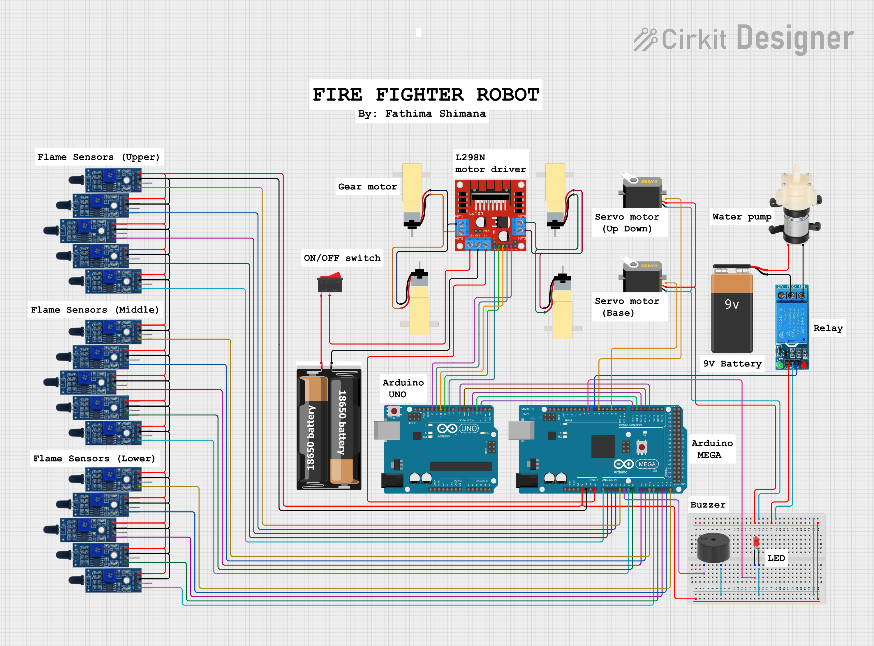
Circuit Documentation
Summary
The circuit in question appears to be a complex system involving various sensors, actuators, power sources, and control units. The primary controllers in the system are an Arduino Mega 2560 and an Arduino UNO, which interface with multiple flame sensors, a buzzer, LEDs, servos, a relay, a water pump, a motor driver, and gearmotors. The circuit is powered by a combination of a 9V battery and a 2x 18650 battery pack. The system seems to be designed for detecting flames and responding to them, possibly in a robotic or automated environment.
Component List
Controllers
- Arduino Mega 2560: A microcontroller board based on the ATmega2560, with numerous digital and analog I/O pins.
- Arduino UNO: A microcontroller board based on the ATmega328P, with a variety of digital and analog I/O pins.
Sensors
- Flame Sensor: A device that can detect the presence of a flame or fire.
Actuators
- Servo: An actuator that can be precisely controlled for angular positioning.
- Mini Diaphragm Water Pump: A pump used for moving water.
- Hobby Gearmotor with 48:1 gearbox: A motor with a gearbox for increased torque.
Power Sources
- 2x 18650 Battery Pack: A battery pack consisting of two 18650 lithium-ion cells.
- 9V Battery: A standard 9V battery used for electronic applications.
Signal Conditioning and Drivers
- 12V Single Channel Relay: An electromechanical switch used for turning high power devices on and off.
- L298N DC Motor Driver: A driver module capable of controlling two DC motors.
Indicators and Sound
- LED (Red): A red light-emitting diode used as an indicator.
- Buzzer: An electronic sounder that can emit a tone when powered.
Switches
- Rocker Switch: A switch that rocks back and forth to open or close the circuit.
Wiring Details
Controllers
- Arduino Mega 2560
- Digital and analog pins connected to various flame sensors and actuators.
- Power (5V) and ground connections distributed to flame sensors and relay module.
Sensors
- Flame Sensors
- VCC pins connected to the 5V output from the Arduino Mega 2560.
- GND pins connected to the ground of the Arduino Mega 2560.
- A0 pins connected to individual analog input pins on the Arduino Mega 2560.
Actuators
- Servos
- VCC pins connected to the 5V output from the Arduino Mega 2560.
- GND pins connected to the ground.
- Pulse pins connected to PWM-capable digital pins on the Arduino Mega 2560.
Power Sources
- 2x 18650 Battery Pack
- VCC and GND connected to the L298N motor driver and the rocker switch.
Signal Conditioning and Drivers
- 12V Single Channel Relay
- VCC and GND connected to the power source and ground.
- IN pin connected to a digital pin on the Arduino Mega 2560 for control.
- COM pin connected to the negative terminal of the 9V battery.
- NO pin connected to the negative terminal of the water pump.
Indicators and Sound
- LED (Red)
- Anode connected to a digital pin on the Arduino Mega 2560.
- Cathode connected to the ground.
- Buzzer
- PIN connected to an analog pin on the Arduino Mega 2560.
- GND connected to the ground.
Switches
- Rocker Switch
- One terminal connected to the VCC of the 2x 18650 battery pack.
- The other terminal connected to the 12V input of the L298N motor driver.
Documented Code
Arduino Mega 2560 Code (sketch.ino)
void setup() {
  // put your setup code here, to run once:

}

void loop() {
  // put your main code here, to run repeatedly:

}
Arduino UNO Code (sketch.ino)
void setup() {
  // put your setup code here, to run once:

}

void loop() {
  // put your main code here, to run repeatedly:

}
Note: The provided code for both microcontrollers is a template with empty setup and loop functions. Actual functionality needs to be implemented based on the specific requirements of the circuit's operation.