
Raspberry Pi Zero W Based Sound Detection System with GLCD Feedback
View and Edit Project In Cirkit Designer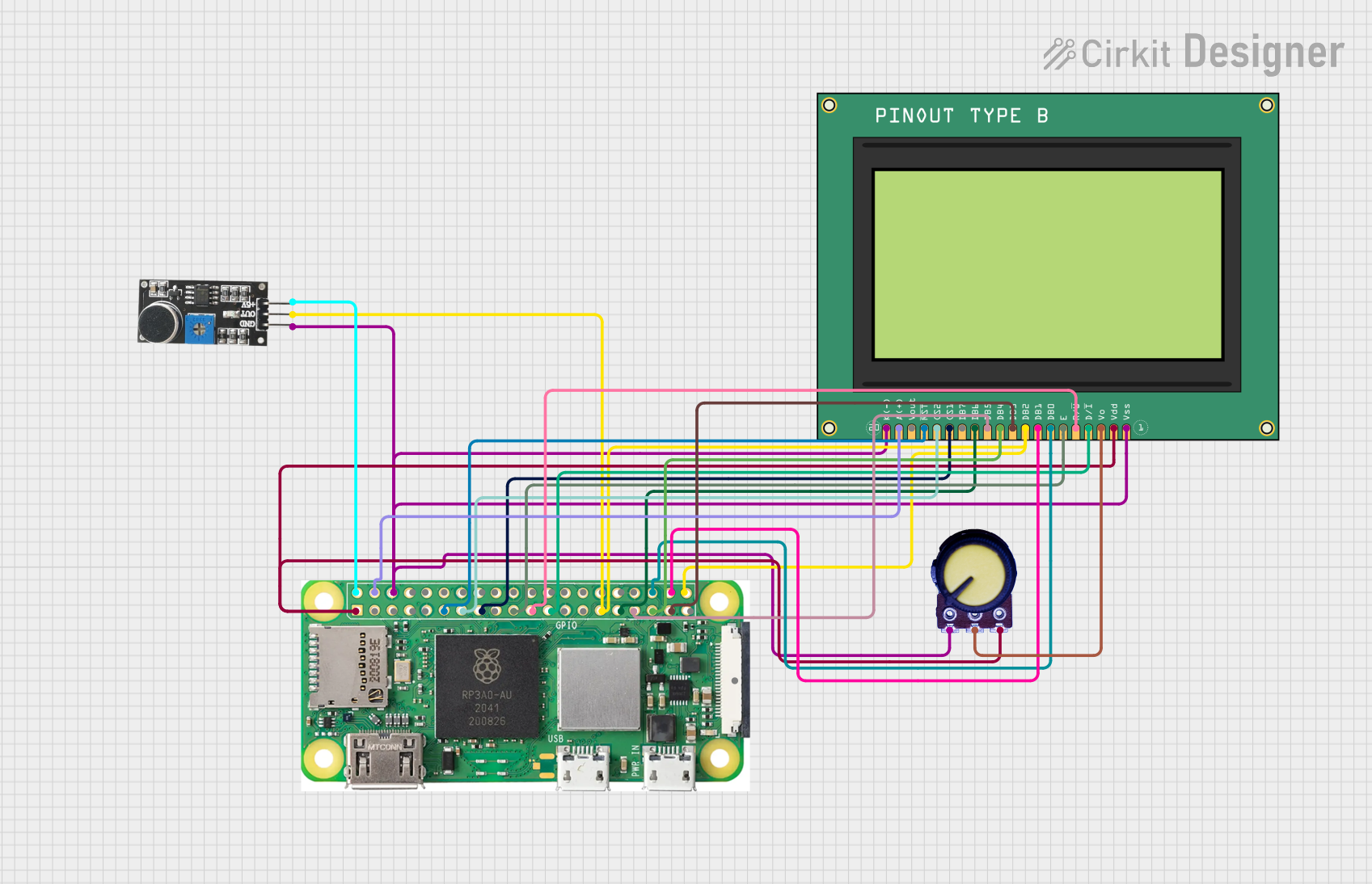
Circuit Documentation
Summary
The circuit in question is designed to interface a Raspberry Pi Zero W with a Graphic LCD Display (GLCD 128x64), a Potentiometer, and a Sound Sensor. The Raspberry Pi Zero W processes audio signals from the Sound Sensor and displays information on the GLCD. The Potentiometer is used to adjust the contrast of the GLCD. The system is capable of detecting specific sound patterns, such as those made by rice weevils, and displaying the results on the GLCD.
Component List
Raspberry Pi Zero W
- A low-cost, compact variant of the Raspberry Pi with wireless LAN and Bluetooth connectivity.
- Pins: 5V, 3V3, multiple GPIOs, GND, CSI (Camera).
Graphic LCD Display (GLCD 128x64)
- A graphical display with a resolution of 128x64 pixels, capable of displaying text and graphics.
- Pins: 20 K(-), 19 A(+), 18 Vout, 17 RST, 16 CS2, 15 CS1, 14 DB7 to 7 DB0, 6 Enable, 5 R/W, 4 D/I, 3 Vo, 2 Vdd, 1 Vss.
Potentiometer
- A three-terminal resistor with an adjustable voltage divider used for adjusting LCD contrast.
- Pins: GND, Output, VCC.
Sound Sensor
- A sensor that detects sound levels in the environment and outputs a signal based on the intensity of the sound.
- Pins: 5V +, OUT, GND.
Wiring Details
Raspberry Pi Zero W
- 5V connected to Sound Sensor 5V + and GLCD 19 A(+).
- 3V3 connected to GLCD 2 Vdd.
- GROUND connected to Sound Sensor GND, GLCD 20 K(-), GLCD 1 Vss, and Potentiometer GND.
- GPIOs connected to various pins on the GLCD for data and control signals.
Graphic LCD Display (GLCD 128x64)
- 19 A(+) and 20 K(-) connected to Raspberry Pi 5V and GROUND for backlight power.
- 17 RST, 16 CS2, 15 CS1, 6 Enable, 5 R/W, 4 D/I, and 14 DB7 to 7 DB0 connected to corresponding GPIOs on the Raspberry Pi for display control and data.
- 3 Vo connected to Potentiometer Output for contrast adjustment.
Potentiometer
- VCC connected to Raspberry Pi 3V3.
- Output connected to GLCD 3 Vo.
- GND connected to Raspberry Pi GROUND.
Sound Sensor
- 5V + connected to Raspberry Pi 5V.
- OUT connected to Raspberry Pi GPIO 21 and GPIO 5.
- GND connected to Raspberry Pi GROUND.
Documented Code
Raspberry Pi Zero W Code
/*
 * This Arduino Sketch is for a Raspberry Pi Zero W connected to a Sound Detector.
 * The Raspberry Pi processes audio signals picked up by the Sound Detector.
 * The audio signals can be analyzed to detect specific sound patterns, such as
 * those made by rice weevils. The Raspberry Pi can connect to a laptop via WiFi
 * or Bluetooth for further processing and analysis.
 */

#include <WiFi.h>
#include <BluetoothSerial.h>

#define ENVELOPE_PIN 0
#define AUDIO_PIN 5
#define GATE_PIN 6

BluetoothSerial SerialBT;

void setup() {
  Serial.begin(115200);
  SerialBT.begin("RaspberryPi"); // Bluetooth device name
  WiFi.begin("yourSSID", "yourPASSWORD");

  pinMode(ENVELOPE_PIN, INPUT);
  pinMode(AUDIO_PIN, INPUT);
  pinMode(GATE_PIN, INPUT);

  while (WiFi.status() != WL_CONNECTED) {
    delay(1000);
    Serial.println("Connecting to WiFi...");
  }
  Serial.println("Connected to WiFi");
}

void loop() {
  int envelopeValue = analogRead(ENVELOPE_PIN);
  int audioValue = analogRead(AUDIO_PIN);
  int gateValue = digitalRead(GATE_PIN);

  Serial.print("Envelope: ");
  Serial.print(envelopeValue);
  Serial.print(" Audio: ");
  Serial.print(audioValue);
  Serial.print(" Gate: ");
  Serial.println(gateValue);

  SerialBT.print("Envelope: ");
  SerialBT.print(envelopeValue);
  SerialBT.print(" Audio: ");
  SerialBT.print(audioValue);
  SerialBT.print(" Gate: ");
  SerialBT.println(gateValue);

  delay(1000); // Adjust delay as needed
}
Graphic LCD Display (GLCD 128x64) Code
/*
 * This Arduino Sketch is for a Graphic LCD Display (GLCD 128x64) connected to
 * a Raspberry Pi Zero W and a Sound Detector. The system analyzes audio signals
 * to detect frequencies in the range of 2kHz to 5kHz, indicating the presence of
 * rice weevils. The result is displayed on the GLCD.
 */

#include <Wire.h>
#include <Adafruit_GFX.h>
#include <Adafruit_PCD8544.h>

#define AUDIO_PIN 21
#define CS1_PIN 22
#define CS2_PIN 27
#define RST_PIN 17
#define ENABLE_PIN 10
#define DI_PIN 11
#define DB0_PIN 16
#define DB1_PIN 20
#define DB2_PIN 21
#define DB3_PIN 26
#define DB4_PIN 19
#define DB5_PIN 13
#define DB6_PIN 6
#define RW_PIN 9

Adafruit_PCD8544 display = Adafruit_PCD8544(CS1_PIN, CS2_PIN, RST_PIN, ENABLE_PIN, DI_PIN, RW_PIN);

void setup() {
  display.begin();
  display.setContrast(50);
  display.clearDisplay();
  display.display();
  pinMode(AUDIO_PIN, INPUT);
}

void loop() {
  int audioValue = analogRead(AUDIO_PIN);
  float frequency = getFrequency(audioValue);
  display.clearDisplay();
  display.setCursor(0, 0);
  if (frequency >= 2000 && frequency <= 5000) {
    display.print("Rice weevils detected");
  } else {
    display.print("No rice weevils detected");
  }
  display.display();
  delay(1000);
}

float getFrequency(int audioValue) {
  // Placeholder function to simulate frequency detection
  // Replace with actual frequency analysis code
  return 3000.0; // Example frequency
}
Sound Sensor Code
/*
 * This Arduino Sketch is for a Sound Sensor connected to a Raspberry Pi Zero W.
 * The system detects sound frequencies and categorizes them into different ranges.
 * The detected frequency range is printed to the Serial Monitor.
 */

#define SOUND_SENSOR_PIN A0

void setup() {
  Serial.begin(115200);
  pinMode(SOUND_SENSOR_PIN, INPUT);
}

void loop() {
  int sensorValue = analogRead(SOUND_SENSOR_PIN);
  float frequency = getFrequency(sensorValue);
  Serial.print("Detected Frequency: ");
  Serial.print(frequency);
  Serial.print(" Hz - ");
  if (frequency < 1000) {
    Serial.println("Low Frequency");
  } else if (frequency < 5000) {
    Serial.println("Medium Frequency");
  } else {
    Serial.println("High Frequency");
  }
  delay(1000);
}

float getFrequency(int sensorValue) {
  // Placeholder function to simulate frequency detection
  // Replace with actual frequency analysis code
  return 3000.0; // Example frequency
}
Note: The provided code snippets are for illustrative purposes and may require further development to function in a real-world scenario. The getFrequency function is a placeholder and should be replaced with actual frequency analysis algorithms.