
Raspberry Pi 5 Controlled Dual Stepper Motor System with IR Sensor Feedback
View and Edit Project In Cirkit Designer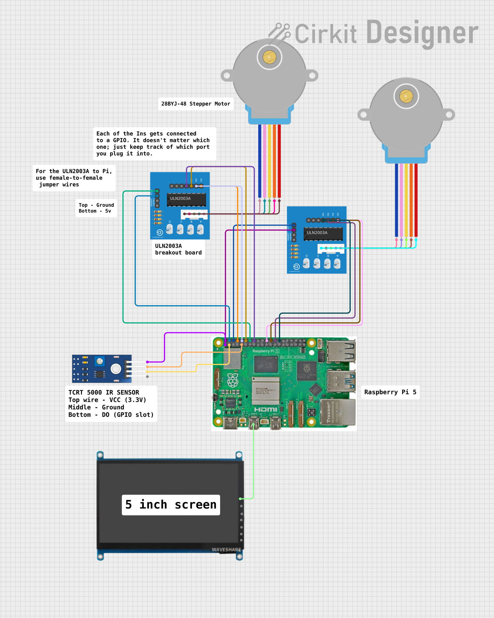
Circuit Documentation
Summary
This circuit primarily consists of a Raspberry Pi 5, two ULN2003A breakout boards, two 28BYJ-48 stepper motors, a TCRT 5000 IR sensor, and a 7 inch WaveShare (H) display. The Raspberry Pi 5 serves as the central processing unit, interfacing with the display, the IR sensor, and controlling the stepper motors through the ULN2003A breakout boards. The IR sensor is used for object detection, and the stepper motors are presumably for precision movement or positioning, commonly found in robotic or automation applications.
Component List
Raspberry Pi 5
- A microcomputer with a variety of I/O options including GPIO pins, HDMI, USB ports, Ethernet, and power inputs.
- Utilized for controlling the stepper motors and reading the IR sensor output.
ULN2003A Breakout Board (x2)
- A board containing the ULN2003A driver IC, which is used for driving stepper motors.
- Each board interfaces with a 28BYJ-48 stepper motor.
28BYJ-48 Stepper Motor (x2)
- A small, 5-wire, unipolar stepper motor used for precise motion control.
TCRT 5000 IR Sensor
- An infrared sensor with digital and analog outputs, used for object detection or distance measurement.
7 inch WaveShare (H) Display
- A 7-inch HDMI display with additional interfaces for power and touch input.
Wiring Details
Raspberry Pi 5
- Micro HDMI 1 connected to the HDMI port of the 7 inch WaveShare (H) display.
- 5V supplies power to both ULN2003A breakout boards.
- GND is connected to the 0V (ground) of both ULN2003A breakout boards and the GND of the TCRT 5000 IR sensor.
- 3.3v supplies power to the VCC of the TCRT 5000 IR sensor.
- GPIO 14, 15, 18, 23 are connected to the inputs In 1 to In 4 of one ULN2003A breakout board.
- GPIO 25, 8, 7, 1 are connected to the inputs In 1 to In 4 of the other ULN2003A breakout board.
- GPIO 2 is connected to the digital output (DO) of the TCRT 5000 IR sensor.
ULN2003A Breakout Board
- +5V connected to the 5V of the Raspberry Pi 5.
- 0V connected to the GND of the Raspberry Pi 5.
- In 1 to In 4 connected to specified GPIO pins on the Raspberry Pi 5 for motor control.
- BLUE, PINK, YELLOW, ORANGE, RED wires connected to corresponding wires of the 28BYJ-48 stepper motors.
28BYJ-48 Stepper Motor
- BLUE, PINK, YELLOW, ORANGE, RED wires connected to corresponding wires on the ULN2003A breakout boards.
TCRT 5000 IR Sensor
- VCC connected to the 3.3v of the Raspberry Pi 5.
- GND connected to the GND of the Raspberry Pi 5.
- DO connected to GPIO 2 of the Raspberry Pi 5.
7 inch WaveShare (H) Display
- HDMI connected to the Micro HDMI 1 of the Raspberry Pi 5.
Documented Code
No code was provided for the microcontrollers in the circuit. The documentation of the code would typically include a description of the functionality, setup, and main loop, along with any functions or libraries used. Since no code is available, this section is left blank. If code becomes available, it should be documented here with comments explaining the purpose and functionality of each section of the code.