Arduino-Controlled Robotic Vehicle with Joystick and L298N Motor Driver
Circuit Documentation
Summary
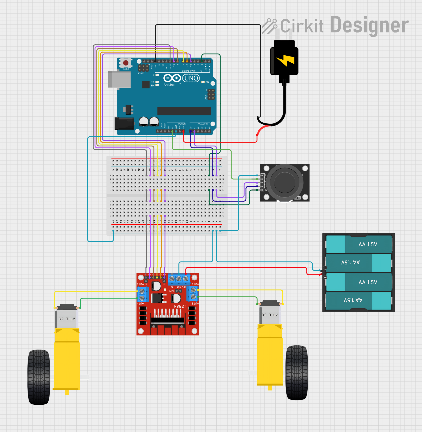
This circuit is designed to control a dual-axis joystick module and a pair of DC gearmotors through an Arduino UNO microcontroller and an L298N DC motor driver. The joystick provides input to the Arduino, which then processes the signals to control the speed and direction of the motors. The motors are powered by a 6V battery pack, while the Arduino and the joystick module are powered by a separate 5V DC source.
Component List
Arduino UNO
- Microcontroller board based on the ATmega328P
- It has 14 digital input/output pins, 6 analog inputs, a 16 MHz quartz crystal, a USB connection, a power jack, an ICSP header, and a reset button.
KY-023 Dual Axis Joystick Module
- A module that provides two analog outputs (one for each axis) and a digital output (button press)
- It has a comfortable thumb joystick and an easy-to-use interface.
L298N DC Motor Driver
- A high-power motor driver capable of driving up to 2 DC motors
- It has 4 input pins for controlling the motors in different directions and 2 enable pins for speed control.
Gearmotor DC Wheels (Left and Right)
- DC gearmotors used to drive the wheels of a vehicle or robot
- Each motor has two connection pins for power.
DC Source 5V
- A power supply module that provides a regulated 5V output
- It powers the Arduino and the joystick module.
Battery AAx4 6V
- A battery pack consisting of 4 AA batteries providing a total of 6V
- It is used to power the L298N motor driver and, subsequently, the DC motors.
Wiring Details
Arduino UNO
A0connected to Joystick ModuleVRyA1connected to Joystick ModuleVRxD2connected to Joystick ModuleSWD5connected to Motor DriverENAD6connected to Motor DriverIN1D7connected to Motor DriverIN2D8connected to Motor DriverIN3D9connected to Motor DriverIN4D10connected to Motor DriverENB5Vconnected to Joystick Module+5VGNDconnected to Joystick ModuleGND, Motor DriverGND, and BatteryGNDVinconnected to DC SourceVCCGNDconnected to DC SourceGND
KY-023 Dual Axis Joystick Module
VRxconnected to ArduinoA1VRyconnected to ArduinoA0SWconnected to ArduinoD2+5Vconnected to Arduino5VGNDconnected to ArduinoGND
L298N DC Motor Driver
ENAconnected to ArduinoD5IN1connected to ArduinoD6IN2connected to ArduinoD7IN3connected to ArduinoD8IN4connected to ArduinoD9ENBconnected to ArduinoD10OUT1connected to Right GearmotorPIN2OUT2connected to Right GearmotorPIN1OUT3connected to Left GearmotorPIN2OUT4connected to Left GearmotorPIN112Vconnected to BatteryVCCGNDconnected to ArduinoGND
Gearmotor DC Wheels Left
PIN1connected to Motor DriverOUT4PIN2connected to Motor DriverOUT3
Gearmotor DC Wheels Right
PIN1connected to Motor DriverOUT2PIN2connected to Motor DriverOUT1
DC Source 5V
VCCconnected to ArduinoVinGNDconnected to ArduinoGND
Battery AAx4 6V
VCCconnected to Motor Driver12VGNDconnected to ArduinoGND
Documented Code
Arduino UNO Code (sketch.ino)
void setup() {
  // put your setup code here, to run once:

}

void loop() {
  // put your main code here, to run repeatedly:

}
This code is a template for the Arduino UNO microcontroller. The setup() function is called once when the microcontroller is first powered on or reset. The loop() function is called repeatedly and contains the main logic that controls the circuit's behavior. The actual implementation details would be added to these functions to read the joystick inputs and control the motor driver accordingly.