Cirkit Designer
Your all-in-one circuit design IDE
Home /
Project Documentation
Arduino Mega 2560 Line-Following Robot with Obstacle Detection
Circuit Documentation
Summary
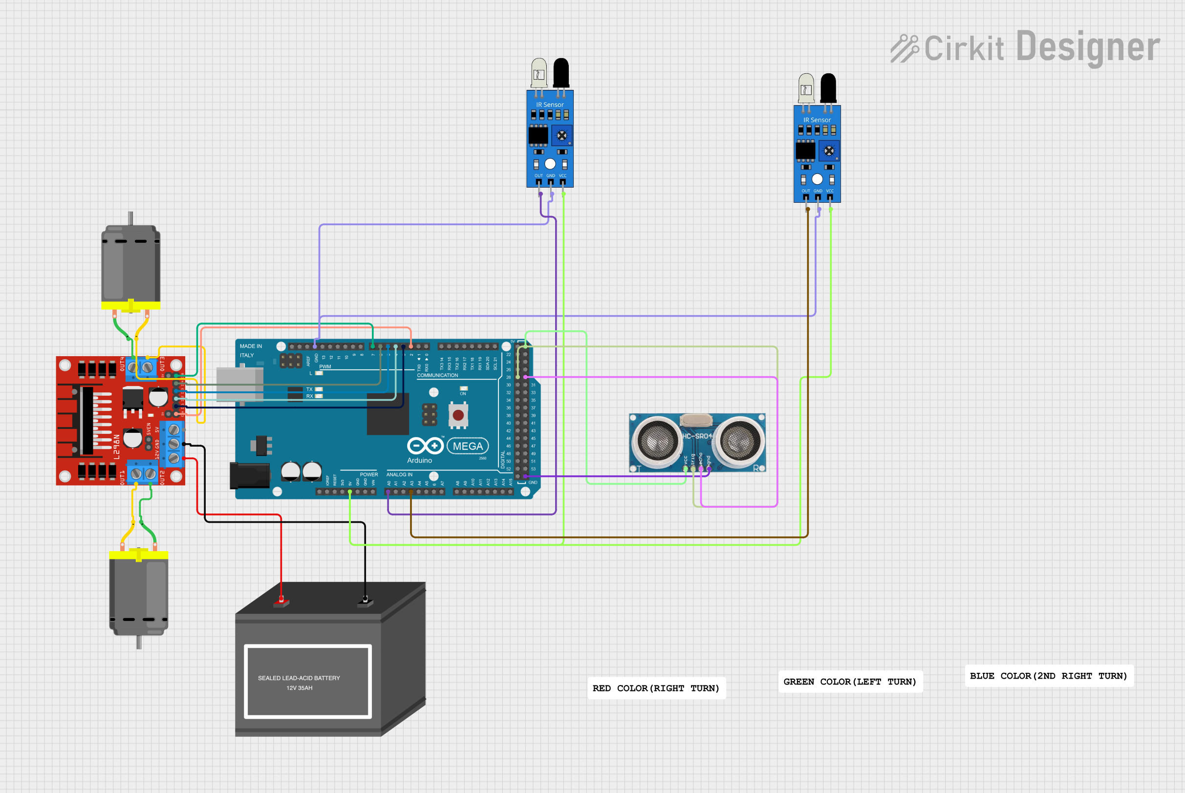
This circuit is designed to control a line-following robot with the capability to detect intersections and obstacles. It uses an Arduino Mega 2560 as the main controller, two IR sensors for line tracking, an ultrasonic sensor for obstacle detection, and a motor driver to control two DC motors. The robot is powered by a 12V battery and is programmed to perform specific maneuvers at intersections and in response to obstacles.
Component List
Arduino Mega 2560
- Microcontroller board based on the ATmega2560
- It has 54 digital input/output pins (of which 15 can be used as PWM outputs), 16 analog inputs, 4 UARTs (hardware serial ports), a 16 MHz crystal oscillator, a USB connection, a power jack, an ICSP header, and a reset button.
DC Motors (x2)
- Electric motors that convert DC electrical energy into mechanical energy.
- Typically used for driving the wheels of the robot.
L298N DC Motor Driver
- A motor driver module that can control up to two DC motors.
- It has two H-bridges and can drive the motors in both directions.
12V Battery (mini)
- A power source for the circuit, providing the necessary voltage for the motors and motor driver.
IR Sensors (x2)
- Infrared sensors used for line tracking.
- They detect the reflection of an infrared light to determine the color of the surface below them.
Ultrasonic Sensor
- A sensor that uses ultrasonic sound waves to measure distance.
- It can detect the presence of obstacles in front of the robot.
Wiring Details
Arduino Mega 2560
5Vpin connected to the VCC pins of both IR sensors and the VCC pin of the Ultrasonic Sensor.GNDpin connected to the GND pins of both IR sensors and the GND pin of the Ultrasonic Sensor.A0pin connected to the OUT pin of the first IR sensor.A3pin connected to the OUT pin of the second IR sensor.D2 PWMpin connected to the ENA pin of the L298N motor driver.D3 PWMpin connected to the IN1 pin of the L298N motor driver.D4 PWMpin connected to the IN2 pin of the L298N motor driver.D5 PWMpin connected to the IN3 pin of the L298N motor driver.D6 PWMpin connected to the IN4 pin of the L298N motor driver.D7 PWMpin connected to the ENB pin of the L298N motor driver.D28pin connected to the Trigger pin of the Ultrasonic Sensor.D29pin connected to the Echo pin of the Ultrasonic Sensor.
DC Motors
- One motor's pins connected to OUT3 and OUT4 of the L298N motor driver.
- The other motor's pins connected to OUT1 and OUT2 of the L298N motor driver.
L298N DC Motor Driver
12Vpin connected to the "+" pin of the 12V Battery.GNDpin connected to the "-" pin of the 12V Battery.
Documented Code
/*
 * Line Following Robot with Intersection Logic
 * This code controls a line-following robot that detects intersections
 * and stops the robot when it detects an obstacle in front, then moves
 * again if the obstacle is not in front. It performs specific actions
 * based on IR sensor readings.
 *
 * - The robot follows a line using two IR sensors.
 * - When both IR sensors detect black, it counts as an intersection.
 * - At the first intersection, the robot turns 90 degrees right.
 * - At the second intersection, the robot turns 180 degrees and returns
 *   to the original position.
 */

// Pin definitions
const int motorENA = 2;
const int motorENB = 7;
const int motorIN1 = 3;
const int motorIN2 = 4;
const int motorIN3 = 5;
const int motorIN4 = 6;
const int irSensor1 = A0;
const int irSensor2 = A3;
const int ultrasonicTrig = 28;
const int ultrasonicEcho = 29;

int intersectionCount = 0;

void setup() {
  // Initialize motor control pins
  pinMode(motorENA, OUTPUT);
  pinMode(motorENB, OUTPUT);
  pinMode(motorIN1, OUTPUT);
  pinMode(motorIN2, OUTPUT);
  pinMode(motorIN3, OUTPUT);
  pinMode(motorIN4, OUTPUT);
  // Initialize IR sensor pins
  pinMode(irSensor1, INPUT);
  pinMode(irSensor2, INPUT);
  // Initialize ultrasonic sensor pins
  pinMode(ultrasonicTrig, OUTPUT);
  pinMode(ultrasonicEcho, INPUT);
  Serial.begin(9600);
}

void loop() {
  // Check for obstacles
  if (detectObstacle()) {
    stopRobot();
  } else {
    followLine();
  }
  Serial.print("Intersections passed: ");
  Serial.println(intersectionCount);
}

bool detectObstacle() {
  digitalWrite(ultrasonicTrig, LOW);
  delayMicroseconds(2);
  digitalWrite(ultrasonicTrig, HIGH);
  delayMicroseconds(10);
  digitalWrite(ultrasonicTrig, LOW);
  long duration = pulseIn(ultrasonicEcho, HIGH);
  long distance = duration * 0.034 / 2;
  return distance < 20; // Obstacle within 20 cm
}

void stopRobot() {
  analogWrite(motorENA, 0);
  analogWrite(motorENB, 0);
}

void followLine() {
  int sensor1 = analogRead(irSensor1);
  int sensor2 = analogRead(irSensor2);
  if (sensor1 < 500 && sensor2 < 500) {
    intersectionCount++;
    if (intersectionCount == 1) {
      turnRight();
    } else if (intersectionCount == 2) {
      turn180();
      intersectionCount = 0;
    }
  } else if (sensor1 < 500) {
    analogWrite(motorENA, 255);
    analogWrite(motorENB, 128);
  } else if (sensor2 < 500) {
    analogWrite(motorENA, 128);
    analogWrite(motorENB, 255);
  } else {
    analogWrite(motorENA, 255);
    analogWrite(motorENB, 255);
  }
}

void turnRight() {
  digitalWrite(motorIN1, HIGH);
  digitalWrite(motorIN2, LOW);
  digitalWrite(motorIN3, LOW);
  digitalWrite(motorIN4, HIGH);
  delay(500);
}

void turn180() {
  digitalWrite(motorIN1, HIGH);
  digitalWrite(motorIN2, LOW);
  digitalWrite(motorIN3, HIGH);
  digitalWrite(motorIN4, LOW);
  delay(1000);
}
This code is responsible for the operation of the line-following robot. It initializes the necessary pins, contains functions to detect obstacles, stop the robot, follow the line, and perform turns. The robot's behavior is determined by the readings from the IR sensors and the ultrasonic sensor.