Arduino-Controlled Dual Stepper Motor Driver with DRV8825
Circuit Documentation
Summary
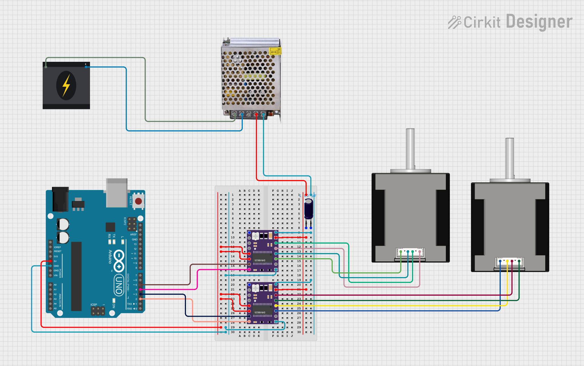
This circuit is designed to control two stepper motors using DRV8825 stepper motor drivers, which are interfaced with an Arduino UNO microcontroller. The circuit includes a power supply unit that provides the necessary voltage to the drivers and motors. An electrolytic capacitor is used to stabilize the power supply to the drivers. The Arduino UNO is programmed to rotate the stepper motors in a specific pattern, with one revolution forward followed by two revolutions backward.
Component List
Arduino UNO
- Microcontroller board based on the ATmega328P
- It has 14 digital input/output pins, 6 analog inputs, a 16 MHz quartz crystal, a USB connection, a power jack, an ICSP header, and a reset button.
DRV 8825
- Stepper motor driver capable of driving up to 2.5A per phase
- It has six control inputs (EN, M0, M1, M2, RST, SLP), two inputs for motor power (VMOT, GND MOTOR), four outputs for motor connections (A1, A2, B1, B2), a fault output (FAULT), and a ground for logic (GND LOGIC).
Nema 17 42-STH48 Stepper Motor
- A four-wire bipolar stepper motor
- It has a step angle of 1.8 degrees and is commonly used in 3D printers, CNC machines, and other precision motion control applications.
Electrolytic Capacitor
- A passive electronic component with a capacitance of 1 microfarad (uF)
- It is used to smooth out voltage fluctuations.
POWER SUPPLY 12V 5AMP
- A power supply unit that converts 220V AC to 12V-24V DC
- It has an input for 220V AC and outputs for ground and 12V-24V DC.
240v Power Source
- The main AC power source for the circuit
- It provides the 220V AC required by the power supply unit.
Wiring Details
Arduino UNO
5Vconnected to DRV 8825 RST and SLP pinsGNDconnected to DRV 8825 GND LOGIC pinsD5connected to DRV 8825 STEP pin (first driver)D4connected to DRV 8825 DIR pin (first driver)D3connected to DRV 8825 STEP pin (second driver)D2connected to DRV 8825 DIR pin (second driver)
DRV 8825 (First and Second Drivers)
VMOTconnected to the positive output of the power supply through an electrolytic capacitorGND MOTORconnected to the ground of the power supply through an electrolytic capacitorRSTandSLPconnected to the 5V output of the Arduino UNOGND LOGICconnected to the GND pin of the Arduino UNOA1,A2,B1,B2connected to the corresponding pins of the Nema 17 stepper motors
Nema 17 42-STH48 Stepper Motor (First and Second Motors)
A1 Green,A2 (black),B1 Blue,B2 Redconnected to the corresponding pins of the DRV 8825 drivers
Electrolytic Capacitor
+connected to the 12V-24V output of the power supply-connected to the ground of the power supply
POWER SUPPLY 12V 5AMP
220V Positive Pole (AC)connected to the live wire of the 240v power source220V Negative Pole (AC)connected to the neutral wire of the 240v power sourceGND (DC)and12V-24V Output (DC)provide power to the DRV 8825 drivers and the electrolytic capacitor
Documented Code
/*
 * This Arduino Sketch controls a stepper motor using a DRV8825 driver.
 * The motor will rotate 1 revolution forward and then 2 revolutions backward.
 */

#define dirPin 2
#define stepPin 3
#define stepsPerRevolution 200

void setup() {
  pinMode(stepPin, OUTPUT);
  pinMode(dirPin, OUTPUT);
}

void loop() {
  // Rotate 1 revolution forward
  digitalWrite(dirPin, HIGH);
  for (int i = 0; i < stepsPerRevolution; i++) {
    digitalWrite(stepPin, HIGH);
    delayMicroseconds(2000);
    digitalWrite(stepPin, LOW);
    delayMicroseconds(2000);
  }
  delay(1000);

  // Rotate 2 revolutions backward
  digitalWrite(dirPin, LOW);
  for (int i = 0; i < 2 * stepsPerRevolution; i++) {
    digitalWrite(stepPin, HIGH);
    delayMicroseconds(2000);
    digitalWrite(stepPin, LOW);
    delayMicroseconds(2000);
  }
  delay(1000);
}
This code is designed to control a stepper motor using the Arduino UNO and a DRV8825 driver. The dirPin and stepPin are defined and set as outputs. In the loop function, the motor is instructed to rotate one revolution in one direction and then two revolutions in the opposite direction, with a delay between each step to control the speed.