ESP32-Controlled Dual DC Motor & Stepper Motor Driver System
Circuit Documentation
Summary
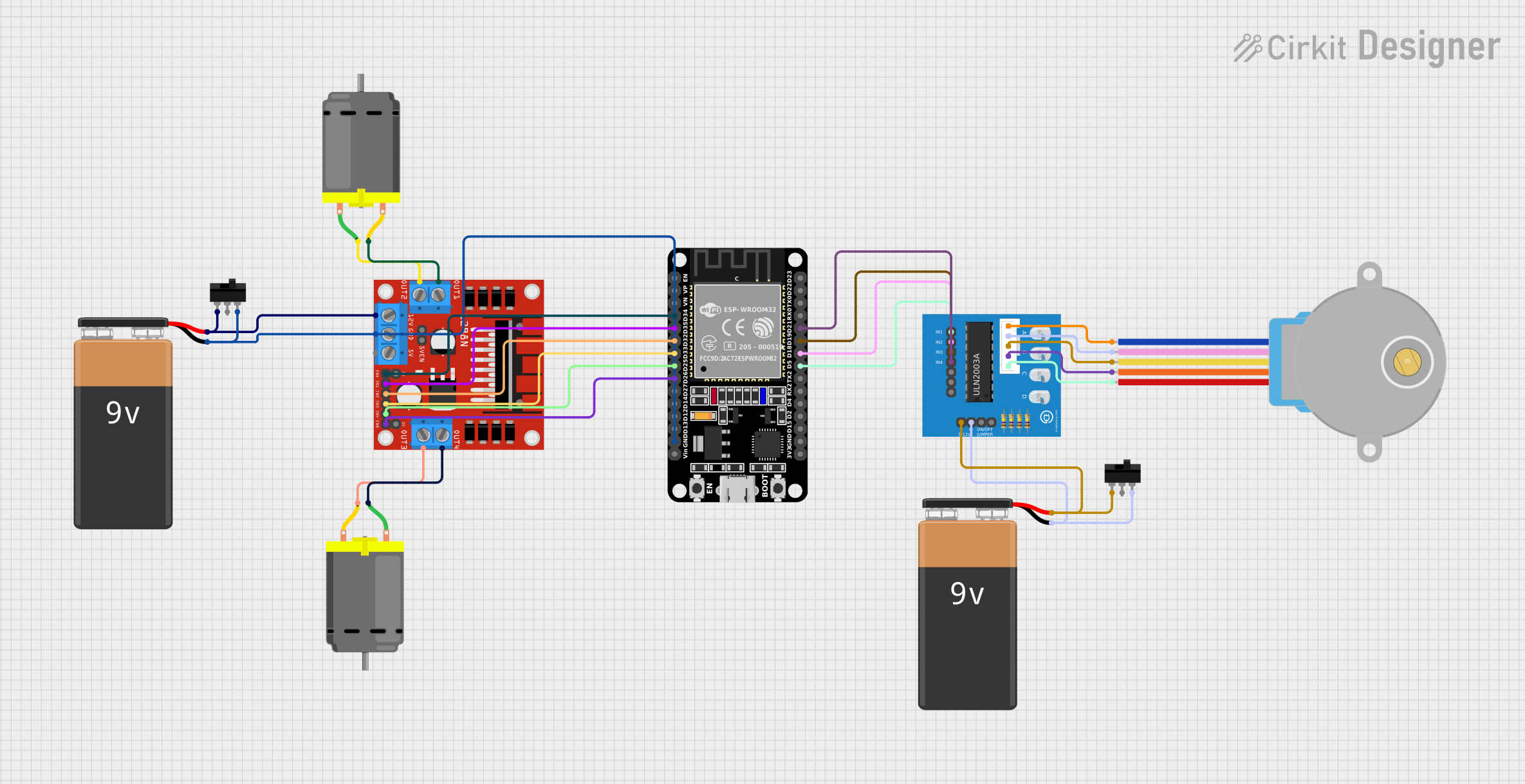
This circuit is designed to control two types of motors: a DC motor and a 28BYJ-48 stepper motor. The DC motor is driven by an L298N motor driver, which is controlled by an ESP32 microcontroller. The stepper motor is driven by a ULN2003A breakout board, also controlled by the ESP32. Power is supplied by two separate 9V batteries, each with a toggle switch for power control. The ESP32 microcontroller is programmed to control the speed and direction of the DC motor and can be adapted to control the stepper motor as well.
Component List
DC Motor
- Description: A standard DC motor used for converting electrical energy into mechanical rotation.
- Pins: pin 1, pin 2
L298N DC Motor Driver
- Description: A motor driver module capable of driving two DC motors or one stepper motor.
- Pins: OUT1, OUT2, 12V, GND, 5V, OUT3, OUT4, 5V-ENA-JMP-I, 5V-ENA-JMP-O, +5V-J1, +5V-J2, ENA, IN1, IN2, IN3, IN4, ENB
9V Battery
- Description: A standard 9V battery used to provide power to the circuit.
- Pins: -, +
Toggle Switch
- Description: A switch used to control the power supply to the circuit components.
- Pins: L1, COM, L2
ESP32 (30 pin)
- Description: A microcontroller with Wi-Fi and Bluetooth capabilities, used for controlling the motors.
- Pins: EN, VP, VN, D34, D35, D32, D33, D25, D26, D27, D14, D12, D13, GND, Vin, D23, D22, TX0, RX0, D21, D19, D18, D5, TX2, RX2, D4, D2, D15, 3V3
28BYJ-48 Stepper Motor
- Description: A small, 5-wire unipolar stepper motor used for precise rotational movement.
- Pins: BLUE, PINK, YELLOW, ORANGE, RED
ULN2003A Breakout Board
- Description: A breakout board for the ULN2003A stepper motor driver IC.
- Pins: In 1, In 2, In 3, In 4, In 5, In 6, In 7, 0V, +5V, ON/OFF jumper switch, BLUE wire, PINK wire, YELLOW wire, ORANGE wire, RED wire
Wiring Details
DC Motor
- Wiring:
- pin 1: Connected to OUT2 of the L298N motor driver.
- pin 2: Connected to OUT1 of the L298N motor driver.
L298N DC Motor Driver
- Wiring:
- ENA: Connected to D34 of the ESP32.
- IN1: Connected to D35 of the ESP32.
- IN2: Connected to D32 of the ESP32.
- IN3: Connected to D33 of the ESP32.
- IN4: Connected to D25 of the ESP32.
- ENB: Connected to D26 of the ESP32.
- GND: Connected to the negative terminal of the 9V Battery and GND of the ESP32.
- 12V: Connected to the positive terminal of the 9V Battery.
- OUT1, OUT2, OUT3, OUT4: Connected to the pins of the DC Motors.
9V Battery
- Wiring:
- +: Connected to the 12V input of the L298N motor driver and the +5V of the ULN2003A breakout board.
- -: Connected to the GND of the L298N motor driver and the 0V of the ULN2003A breakout board.
Toggle Switch
- Wiring:
- L1: Connected to the positive terminal of the 9V Battery.
- COM: Not connected.
- L2: Connected to the GND of the L298N motor driver and the 0V of the ULN2003A breakout board.
ESP32 (30 pin)
- Wiring:
- D34: Connected to ENA of the L298N motor driver.
- D35: Connected to IN1 of the L298N motor driver.
- D32: Connected to IN2 of the L298N motor driver.
- D33: Connected to IN3 of the L298N motor driver.
- D25: Connected to IN4 of the L298N motor driver.
- D26: Connected to ENB of the L298N motor driver.
- GND: Connected to the GND of the L298N motor driver.
- D21, D19, D18, D5: Connected to In 4, In 3, In 2, In 1 of the ULN2003A breakout board respectively.
28BYJ-48 Stepper Motor
- Wiring:
- BLUE: Connected to the BLUE wire of the ULN2003A breakout board.
- PINK: Connected to the PINK wire of the ULN2003A breakout board.
- YELLOW: Connected to the YELLOW wire of the ULN2003A breakout board.
- ORANGE: Connected to the ORANGE wire of the ULN2003A breakout board.
- RED: Connected to the RED wire of the ULN2003A breakout board.
ULN2003A Breakout Board
- Wiring:
- In 1: Connected to D5 of the ESP32.
- In 2: Connected to D18 of the ESP32.
- In 3: Connected to D19 of the ESP32.
- In 4: Connected to D21 of the ESP32.
- 0V: Connected to the negative terminal of the 9V Battery.
- +5V: Connected to the positive terminal of the 9V Battery.
- BLUE wire, PINK wire, YELLOW wire, ORANGE wire, RED wire: Connected to the corresponding wires of the 28BYJ-48 stepper motor.
Documented Code
// Motor A
int motor1Pin1 = 27;
int motor1Pin2 = 26;
int enable1Pin = 14;

// Setting PWM properties
const int freq = 30000;
const int pwmChannel = 0;
const int resolution = 8;
int dutyCycle = 200;

void setup() {
  // sets the pins as outputs:
  pinMode(motor1Pin1, OUTPUT);
  pinMode(motor1Pin2, OUTPUT);
  pinMode(enable1Pin, OUTPUT);

  // configure LEDC PWM
  ledcAttachChannel(enable1Pin, freq, resolution, pwmChannel);

  Serial.begin(115200);

  // testing
  Serial.print("Testing DC Motor...");
}

void loop() {
  // Move the DC motor forward at maximum speed
  Serial.println("Moving Forward");
  digitalWrite(motor1Pin1, LOW);
  digitalWrite(motor1Pin2, HIGH);
  delay(2000);

  // Stop the DC motor
  Serial.println("Motor stopped");
  digitalWrite(motor1Pin1, LOW);
  digitalWrite(motor1Pin2, LOW);
  delay(1000);

  // Move DC motor backwards at maximum speed
  Serial.println("Moving Backwards");
  digitalWrite(motor1Pin1, HIGH);
  digitalWrite(motor1Pin2, LOW);
  delay(2000);

  // Stop the DC motor
  Serial.println("Motor stopped");
  digitalWrite(motor1Pin1, LOW);
  digitalWrite(motor1Pin2, LOW);
  delay(1000);

  // Move DC motor forward with increasing speed
  digitalWrite(motor1Pin1, HIGH);
  digitalWrite(motor1Pin2, LOW);
  while (dutyCycle <= 255){
    ledcWrite(enable1Pin, dutyCycle);
    Serial.print("Forward with duty cycle: ");
    Serial.println(dutyCycle);
    dutyCycle = dutyCycle + 5;
    delay(500);
  }
  dutyCycle = 200;
}
This code is designed to control a DC motor using the ESP32 microcontroller. It sets up PWM for speed control and then cycles the motor forward, backward, and varies the speed. The pins used in the code correspond to the ESP32 microcontroller and must be connected to the appropriate pins on the L298N motor driver for proper operation.