
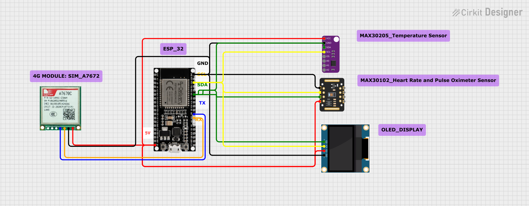
Circuit Documentation
Summary
This circuit utilizes an ESP32 microcontroller to measure heart rate and oxygen levels using the MAX30102 sensor and displays the values on a 0.96" OLED screen. The MAX30205 sensor is also connected but not used in the current sketch. Additionally, the Sim A7670c module is connected for future use.
Component List
ESP32 38 PINS
- Description: A powerful microcontroller with built-in Wi-Fi and Bluetooth capabilities.
- Pins: GND, G23, G22, TXD, RXD, G21, G19, G18, G5, G17, G16, G4, G0, G2, G15, SDI, SD0, CLK, 3V3, EN, SP, SN, G34, G35, G32, 33, G25, G26, G27, G14, G12, G13, SD2, SD3, 5V
MAX30102
- Description: A sensor used for measuring heart rate and oxygen levels.
- Pins: VIN, SDA, SCL, GND, RD, IRD, INT
MAX30205
- Description: A temperature sensor.
- Pins: VCC, GND, SDA, SCL, OS, A0, A1, A2
Sim A7670c
- Description: A GSM/GPRS module for future use.
- Pins: Vin, Gnd, Tx, Rx
0.96" OLED
- Description: A small OLED display used to show heart rate and oxygen levels.
- Pins: GND, VDD, SCK, SDA
Wiring Details
ESP32 38 PINS
- GND: Connected to GND of MAX30205, 0.96" OLED, Sim A7670c, and MAX30102.
- G22: Connected to SCL of MAX30205, SCK of 0.96" OLED, and SCL of MAX30102.
- G21: Connected to SDA of MAX30205, SDA of 0.96" OLED, and SDA of MAX30102.
- G17: Connected to Rx of Sim A7670c.
- G16: Connected to Tx of Sim A7670c.
- 5V: Connected to VCC of MAX30205, VDD of 0.96" OLED, Vin of Sim A7670c, and VIN of MAX30102.
MAX30102
- VIN: Connected to 5V of ESP32.
- SDA: Connected to G21 of ESP32.
- SCL: Connected to G22 of ESP32.
- GND: Connected to GND of ESP32.
MAX30205
- VCC: Connected to 5V of ESP32.
- GND: Connected to GND of ESP32.
- SDA: Connected to G21 of ESP32.
- SCL: Connected to G22 of ESP32.
Sim A7670c
- Vin: Connected to 5V of ESP32.
- Gnd: Connected to GND of ESP32.
- Tx: Connected to G16 of ESP32.
- Rx: Connected to G17 of ESP32.
0.96" OLED
- GND: Connected to GND of ESP32.
- VDD: Connected to 5V of ESP32.
- SCK: Connected to G22 of ESP32.
- SDA: Connected to G21 of ESP32.
Code Documentation
/*
 * This Arduino Sketch uses an ESP32 to measure heart rate and oxygen levels
 * using the MAX30102 sensor and displays the values on a 0.96" OLED screen.
 * The MAX30205 sensor is also connected but not used in this sketch.
 * The Sim A7670c module is connected for future use.
 */

#include <Wire.h>
#include <Adafruit_GFX.h>
#include <Adafruit_SSD1306.h>
#include <Adafruit_Sensor.h>
#include <Adafruit_MAX30105.h>

#define SCREEN_WIDTH 128
#define SCREEN_HEIGHT 64
#define OLED_RESET    -1
Adafruit_SSD1306 display(SCREEN_WIDTH, SCREEN_HEIGHT, &Wire, OLED_RESET);
Adafruit_MAX30105 max30102;

void setup() {
  Serial.begin(115200);
  if(!display.begin(SSD1306_I2C_ADDRESS, OLED_RESET)) {
    Serial.println(F("SSD1306 allocation failed"));
    for(;;);
  }
  display.display();
  delay(2000);
  display.clearDisplay();
  display.setTextSize(1);
  display.setTextColor(SSD1306_WHITE);
  if (!max30102.begin(Wire, I2C_SPEED_FAST)) {
    Serial.println(F("MAX30102 not found. Please check wiring."));
    for(;;);
  }
  max30102.setup();
  max30102.setPulseAmplitudeRed(0x0A);
  max30102.setPulseAmplitudeGreen(0);
}

void loop() {
  display.clearDisplay();
  display.setCursor(0,0);
  display.print(F("Heart Rate: "));
  display.print(max30102.getIR());
  display.print(F(" bpm"));
  display.setCursor(0,10);
  display.print(F("Oxygen: "));
  display.print(max30102.getRed());
  display.print(F(" %SpO2"));
  display.display();
  delay(1000);
}
This code initializes the OLED display and the MAX30102 sensor. It then enters a loop where it continuously reads the heart rate and oxygen levels from the MAX30102 sensor and displays these values on the OLED screen.