Cirkit Designer
Your all-in-one circuit design IDE
Home /
Project Documentation
Wi-Fi Controlled Environmental Monitoring System with Motorized Actuator
Circuit Documentation
Summary
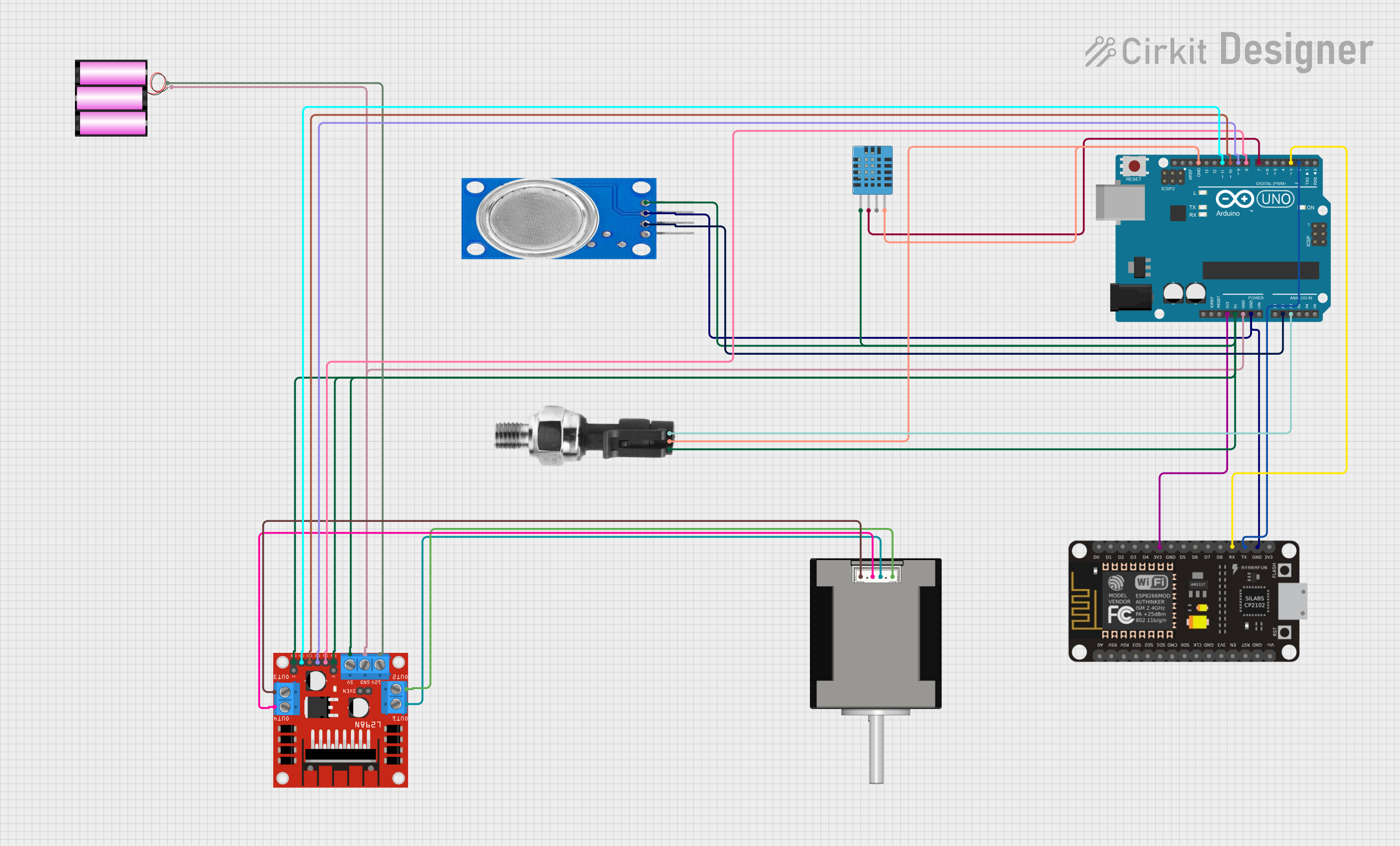
This circuit integrates a variety of components including microcontrollers, sensors, a motor driver, and a stepper motor to form a complex system. The primary microcontroller is an Arduino UNO, which interfaces with an ESP-8266 Controller for Wi-Fi capabilities, a DHT11 humidity and temperature sensor, an MQ135 air quality sensor, an industrial pressure sensor, and a Nema 17 stepper motor through an L298N motor driver. The system is powered by a 12V battery, and the Arduino UNO regulates power to the 3.3V and 5V components.
Component List
Microcontrollers
- Arduino UNO: A microcontroller board based on the ATmega328P, featuring digital and analog I/O pins.
- ESP-8266 Controller: A Wi-Fi capable microcontroller with a range of GPIO pins.
Sensors
- MQ135: An air quality sensor for detecting a wide range of gases, including NH3, NOx, alcohol, benzene, smoke, and CO2.
- DHT11 Humidity and Temperature Sensor: A basic, low-cost digital sensor for measuring ambient temperature and humidity.
- Industrial Pressure Sensor: A sensor for measuring pressure with an analog output signal.
Actuators
- Nema 17 42-STH48: A stepper motor commonly used for precision control in CNC machines and 3D printers.
Power
- Battery 12V: A 12-volt battery providing the main power source for the motor and motor driver.
Motor Driver
- L298N DC Motor Driver: A dual H-bridge motor driver capable of driving a pair of DC motors or a stepper motor.
Wiring Details
Arduino UNO
3.3Vconnected to ESP-8266 Controller3V35Vconnected to:- DHT11 Sensor
VDD - Industrial Pressure Sensor
DC+ - MQ135 Sensor
VCC - L298N Motor Driver
ENA,ENB, and5V
- DHT11 Sensor
GNDconnected to:- Battery
(-) - L298N Motor Driver
GND - MQ135 Sensor
GND - ESP-8266 Controller
GND - DHT11 Sensor
GND - Industrial Pressure Sensor
DC-
- Battery
A1connected to MQ135 SensorA0A2connected to Industrial Pressure SensorSignalD11connected to L298N Motor DriverIN4D10connected to L298N Motor DriverIN3D9connected to L298N Motor DriverIN2D8connected to L298N Motor DriverIN1D7connected to DHT11 SensorDATAD3connected to ESP-8266 ControllerRXD2connected to ESP-8266 ControllerTX
ESP-8266 Controller
RXconnected to Arduino UNOD3TXconnected to Arduino UNOD23V3connected to Arduino UNO3.3VGNDconnected to Arduino UNOGND
MQ135
VCCconnected to Arduino UNO5VGNDconnected to Arduino UNOGNDA0connected to Arduino UNOA1
DHT11 Humidity and Temperature Sensor
VDDconnected to Arduino UNO5VDATAconnected to Arduino UNOD7GNDconnected to Arduino UNOGND
Industrial Pressure Sensor
DC+connected to Arduino UNO5VSignalconnected to Arduino UNOA2DC-connected to Arduino UNOGND
L298N DC Motor Driver
ENAandENBconnected to Arduino UNO5VIN1connected to Arduino UNOD8IN2connected to Arduino UNOD9IN3connected to Arduino UNOD10IN4connected to Arduino UNOD11OUT1connected to Nema 17A1 GreenOUT2connected to Nema 17A2 (black)OUT3connected to Nema 17B1 BlueOUT4connected to Nema 17B2 Red12Vconnected to Battery+GNDconnected to Arduino UNOGND
Nema 17 42-STH48
A1 Greenconnected to L298N Motor DriverOUT1A2 (black)connected to L298N Motor DriverOUT2B1 Blueconnected to L298N Motor DriverOUT3B2 Redconnected to L298N Motor DriverOUT4
Battery 12V
+connected to L298N Motor Driver12V-connected to Arduino UNOGND
Documented Code
Arduino UNO Code (sketch.ino)
void setup() {
  // put your setup code here, to run once:

}

void loop() {
  // put your main code here, to run repeatedly:

}
Note: The provided code for the Arduino UNO is a template with empty setup and loop functions. This code should be expanded with the necessary initialization and operational logic to control the connected components.