Arduino UNO Controlled Multi-Input Interface with RTC and Display
Circuit Documentation
Summary
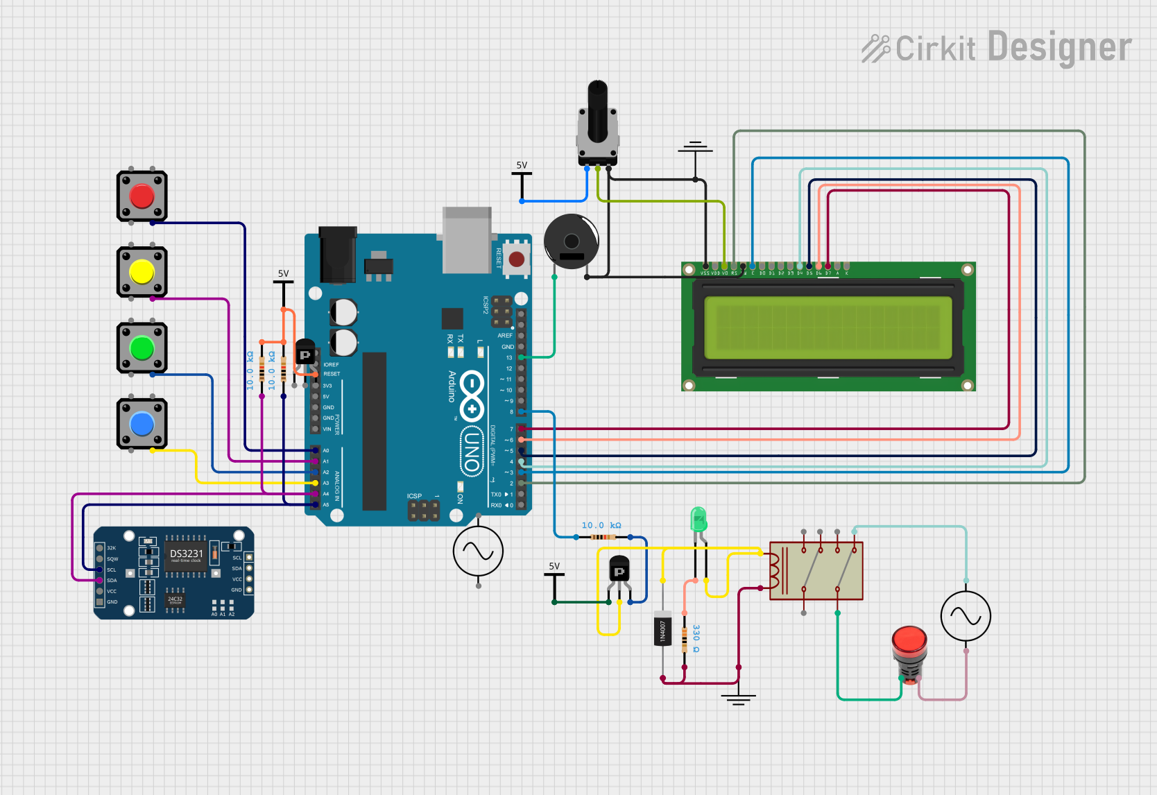
This document provides a detailed overview of a circuit designed to interface with an Arduino UNO microcontroller. The circuit includes various components such as pushbuttons, a piezo buzzer, a rotary potentiometer, resistors, transistors, a relay, a lamp, diodes, an LCD display, and a DS3231 Real-Time Clock (RTC) module. The circuit is powered by Vcc and GND connections and includes an AC supply for the relay and lamp. The Arduino UNO is programmed to interact with these components, although the specific functionality is not detailed in the provided code.
Component List
Pushbutton
- A momentary switch that can be used to input a signal to the Arduino when pressed.
GND
- A ground reference point for the circuit.
Arduino UNO
- A microcontroller board based on the ATmega328P, with digital and analog I/O pins.
Piezo Buzzer
- An electronic device that emits sound when an electrical signal is applied.
Rotary Potentiometer
- A variable resistor with a knob that can be turned to adjust resistance.
Vcc
- A power supply connection point for the circuit.
Resistor
- A passive two-terminal electrical component that implements electrical resistance.
DS3231 RTC
- A real-time clock module for keeping accurate time.
PNP Transistor (EBC and ECB)
- A type of bipolar junction transistor used for amplification and switching.
1N4007 Rectifier Diode
- A diode that allows current to flow in only one direction.
LED: Two Pin (green)
- A light-emitting diode that emits green light when powered.
Ac Supply
- An alternating current power source.
LCD Display 16x2
- A liquid crystal display capable of displaying 16 characters per line on 2 lines.
Relay
- An electrically operated switch that can control a circuit by a separate low-power signal.
Lamp Red
- A red lamp that lights up when powered.
Wiring Details
Pushbutton
- Connected to various analog pins on the Arduino UNO for input signals.
Arduino UNO
- Reset pin connected through resistors to Vcc.
- Analog pins A0-A3 connected to pushbuttons.
- Analog pins A4 and A5 connected to the DS3231 RTC module via resistors.
- Digital pins D2-D8 connected to the LCD display and piezo buzzer.
- Ground and power connections as required.
Piezo Buzzer
- Connected to digital pin D13 on the Arduino UNO.
Rotary Potentiometer
- Wiper connected to the VO pin of the LCD display.
- One leg connected to Vcc, the other to ground.
Resistor
- Various resistors used for pull-up configurations and current limiting.
DS3231 RTC
- SDA and SCL pins connected to the Arduino UNO for I2C communication.
PNP Transistor (ECB)
- Used to control the relay coil.
1N4007 Rectifier Diode
- Connected across the relay coil to prevent back EMF.
LED: Two Pin (green)
- Connected with a current-limiting resistor to the PNP transistor.
Ac Supply
- Provides power to the relay and the red lamp.
LCD Display 16x2
- Data pins DB4-DB7 connected to digital pins D4-D7 on the Arduino UNO.
- Control pins E and RS connected to digital pins D3 and D2, respectively.
- RW, VSS, and VO pins connected to ground, with VO also connected to the potentiometer.
Relay
- Controls the AC supply to the red lamp.
- Coil driven by the PNP transistor and protected by the diode.
Lamp Red
- Powered by the AC supply and controlled by the relay.
Documented Code
void setup() {
  // put your setup code here, to run once:

}

void loop() {
  // put your main code here, to run repeatedly:

}
The provided code is a template with empty setup() and loop() functions, which are the entry points for Arduino code. The setup() function is called once when the program starts and is used to initialize settings. The loop() function runs repeatedly, allowing the program to change and respond. The actual implementation of the circuit's functionality would be placed within these functions.