
ESP32 and MCP2515 CAN Bus Interface with Potentiometer Control
View and Edit Project In Cirkit Designer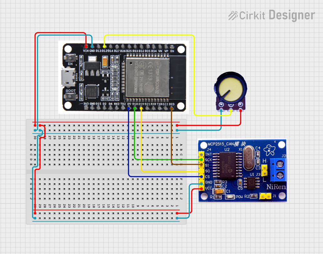
Circuit Documentation
Summary
This document provides a detailed overview of a circuit that includes an ESP32 microcontroller, an MCP2515 CAN controller, and a potentiometer. The circuit is designed to interface the ESP32 with the MCP2515 for CAN communication and to read analog values from the potentiometer.
Component List
ESP32
- Description: A powerful microcontroller with built-in Wi-Fi and Bluetooth capabilities.
- Pins: EN, VP, VN, D34, D35, D32, D33, D25, D26, D27, D14, D12, D13, GND, VIN, 3V3, D15, D2, D4, RX2, TX2, D5, D18, D19, D21, RX0, TX0, D22, D23, BOOT
MCP2515
- Description: A CAN controller that interfaces with microcontrollers via SPI.
- Pins: INT, SCK, SI, SO, CS, GND, VCC, H, L
Potentiometer
- Description: A variable resistor used to adjust voltage levels.
- Pins: GND, Output, VCC
Wiring Details
ESP32
- VIN: Connected to VCC of the Potentiometer and MCP2515
- GND: Connected to GND of the Potentiometer and MCP2515
- D12: Connected to Output of the Potentiometer
- D5: Connected to CS of the MCP2515
- D18: Connected to SCK of the MCP2515
- D19: Connected to SO of the MCP2515
- D23: Connected to SI of the MCP2515
MCP2515
- VCC: Connected to VIN of the ESP32 and VCC of the Potentiometer
- GND: Connected to GND of the ESP32 and GND of the Potentiometer
- CS: Connected to D5 of the ESP32
- SCK: Connected to D18 of the ESP32
- SO: Connected to D19 of the ESP32
- SI: Connected to D23 of the ESP32
Potentiometer
- VCC: Connected to VIN of the ESP32 and VCC of the MCP2515
- GND: Connected to GND of the ESP32 and GND of the MCP2515
- Output: Connected to D12 of the ESP32
Code
There is no code provided for this circuit.
This documentation provides a comprehensive overview of the components and their interconnections in the circuit. The ESP32 microcontroller interfaces with the MCP2515 CAN controller via SPI and reads analog values from the potentiometer.