Dual ESP32-CAM and Arduino Mega 2560 Serial Communication Interface
Circuit Documentation
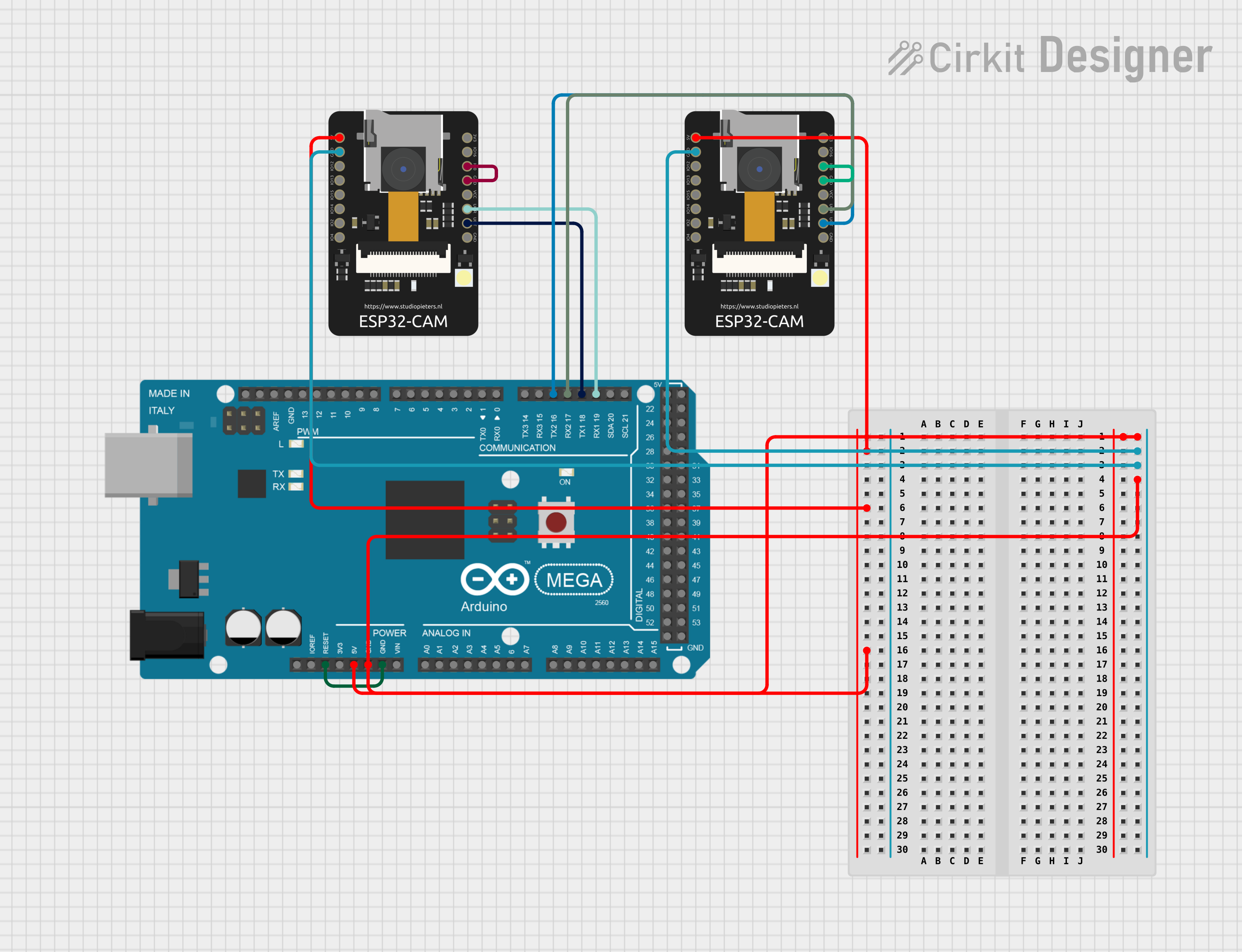
Summary of the Circuit
The circuit consists of two ESP32-CAM modules and one Arduino Mega 2560 microcontroller. The ESP32-CAM modules are connected to the Arduino Mega 2560 for power and serial communication. Ground and power connections are shared among all components to ensure a common reference point and power distribution. Additionally, the ESP32-CAM modules have a GPIO pin (IO0) connected to their respective ground pins, likely for enabling a specific boot mode or configuration. The Arduino Mega 2560 controls an LED connected to pin D13, which blinks with a specified pattern.
Component List
ESP32 - CAM
- Description: A small-sized ESP32-based module with Wi-Fi and camera capabilities.
- Pins: 5V, GND, IO12, IO13, IO15, IO14, IO2, IO4, VOT, VOR, VCC, IO0, IO16, 3V3
Arduino Mega 2560
- Description: A microcontroller board based on the ATmega2560 with numerous digital and analog I/O pins.
- Pins: IOREF, RESET, 3V3, 5V, GND, VIN, A0-A15, D0-D53, AREF, SDA, SCL, and various PWM-capable pins.
Wiring Details
ESP32 - CAM 1
- 5V: Connected to 5V on Arduino Mega 2560
- GND: Connected to GND on Arduino Mega 2560 and IO0 on ESP32 - CAM 1
- VOT: Connected to D18/TX1 on Arduino Mega 2560
- VOR: Connected to D19/RX1 on Arduino Mega 2560
ESP32 - CAM 2
- 5V: Connected to 5V on Arduino Mega 2560
- GND: Connected to GND on Arduino Mega 2560 and IO0 on ESP32 - CAM 2
- VOT: Connected to D16 PWM/TX2 on Arduino Mega 2560
- VOR: Connected to D17 PWM/RX2 on Arduino Mega 2560
Arduino Mega 2560
- 5V: Connected to 5V on both ESP32 - CAM modules
- GND: Connected to GND on both ESP32 - CAM modules and RESET on Arduino Mega 2560
- D18/TX1: Connected to VOT on ESP32 - CAM 1
- D19/RX1: Connected to VOR on ESP32 - CAM 1
- D16 PWM/TX2: Connected to VOT on ESP32 - CAM 2
- D17 PWM/RX2: Connected to VOR on ESP32 - CAM 2
- D13: Configured as an output to control an LED
Documented Code
Arduino Mega 2560 Code
/*
 * This Arduino Sketch controls an LED connected to pin D13.
 * The LED will turn on for one second, then turn off for two seconds,
 * repeating this cycle indefinitely.
 */

void setup() {
  // Initialize digital pin D13 as an output.
  pinMode(13, OUTPUT);
}

void loop() {
  // Turn the LED on (HIGH is the voltage level)
  digitalWrite(13, HIGH);
  // Wait for one second
  delay(1000);
  // Turn the LED off by making the voltage LOW
  digitalWrite(13, LOW);
  // Wait for two seconds
  delay(2000);
}
This code is stored in a file named sketch.ino and is intended to run on the Arduino Mega 2560. It sets up pin D13 as an output to control an LED. In the loop function, the LED is turned on for one second and then turned off for two seconds, creating a blinking pattern.