
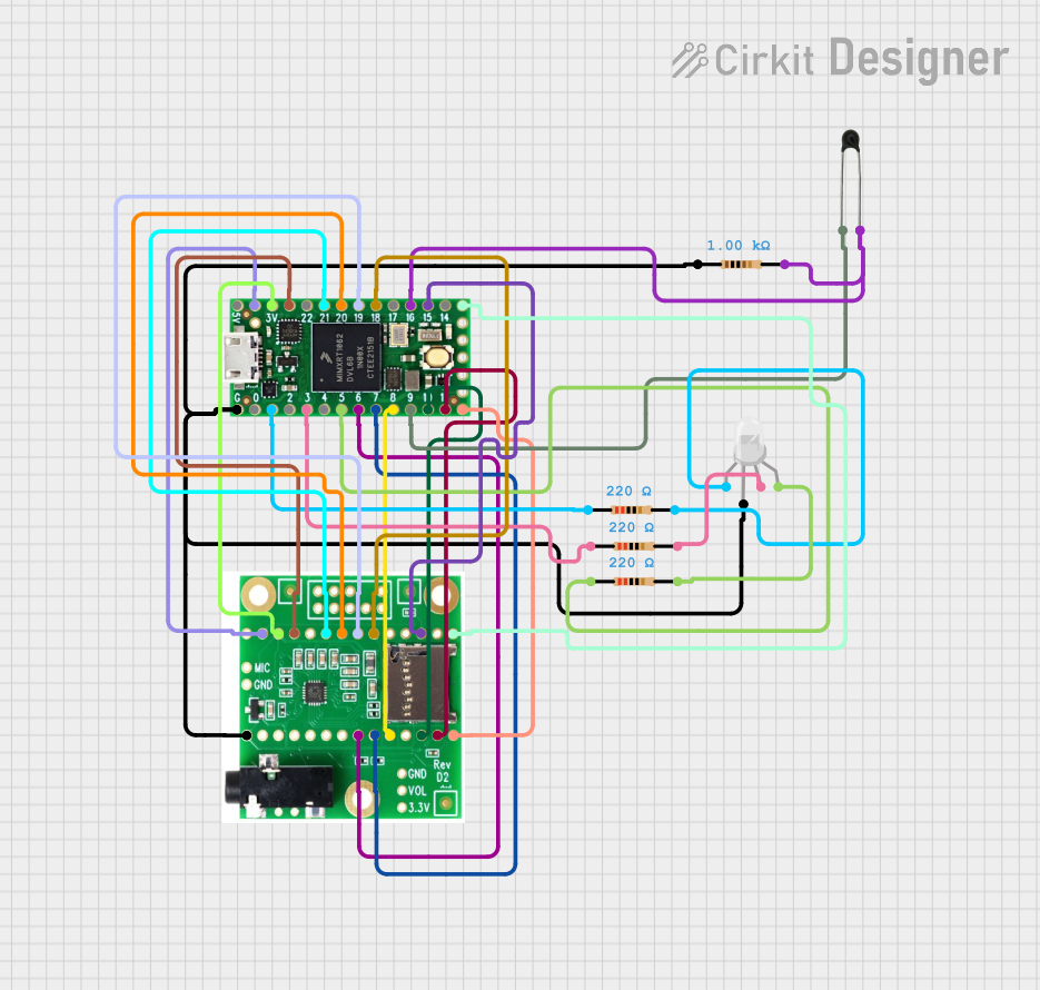
Circuit Documentation
Summary
This circuit integrates a Teensy 4.0 microcontroller with a Teensy Audio Shield and an RGB LED, along with an NTC thermistor and several resistors. The Teensy 4.0 serves as the central processing unit, interfacing with the audio shield for audio processing capabilities. The RGB LED provides visual feedback or user interface, while the NTC thermistor allows for temperature sensing. The resistors are used for current limiting and voltage division as required by the RGB LED and the NTC thermistor.
Component List
Teensy 4.0
- Description: A high-performance microcontroller board based on the ARM Cortex-M7 processor.
- Pins: 5V, GND, 3V, digital pins (0-23), analog pins (A0-A9).
Teensy Audio Shield
- Description: An audio adapter board designed to work with the Teensy microcontroller for audio processing tasks.
- Pins: GND, 3.3V, MEMCS, DIN, DOUT, SDCS, MOSI, MISO, MCLK, BCLK, LRCLK, SCL, SDA, VOL, SCK.
RGB LED (Wokwi compatible)
- Description: A multicolor LED capable of displaying a wide range of colors.
- Pins: R (Red), COM (Common Anode/Cathode), G (Green), B (Blue).
NTC (Negative Temperature Coefficient Thermistor)
- Description: A temperature-sensitive resistor whose resistance decreases as the temperature increases.
- Pins: A0, A1.
Resistor
- Description: A passive two-terminal electrical component that implements electrical resistance as a circuit element.
- Properties: Various resistance values (220 Ohms, 1000 Ohms).
Wiring Details
Teensy 4.0
- GND connected to Teensy Audio Shield GND, RGB LED COM, and NTC A1 through a 1000 Ohm resistor.
- 3V connected to Teensy Audio Shield 3.3V.
- Pins 23, 21, 20, 19, 18, 15, 13, 12, 11, 10, 8, 7, 6 connected to corresponding pins on the Teensy Audio Shield for audio data and control signals.
- Pin 16 connected to NTC A1 through a 1000 Ohm resistor.
- Pin 9 connected to NTC A0.
- Pins 5, 3, 1 connected to RGB LED R, G, B through 220 Ohm resistors respectively.
Teensy Audio Shield
- Wired to Teensy 4.0 as described above.
- GND connected to Teensy 4.0 GND and RGB LED COM.
- 3.3V connected to Teensy 4.0 3V.
RGB LED (Wokwi compatible)
- R connected to Teensy 4.0 pin 5 through a 220 Ohm resistor.
- G connected to Teensy 4.0 pin 3 through a 220 Ohm resistor.
- B connected to Teensy 4.0 pin 1 through a 220 Ohm resistor.
- COM connected to Teensy 4.0 GND.
NTC
- A0 connected to Teensy 4.0 pin 9.
- A1 connected to Teensy 4.0 pin 16 through a 1000 Ohm resistor.
Resistor
- 220 Ohm resistors connected between Teensy 4.0 pins 5, 3, 1 and RGB LED R, G, B.
- 1000 Ohm resistor connected between Teensy 4.0 pin 16 and NTC A1.
Documented Code
No code has been provided for the microcontroller. The documentation of the code would typically include a description of the functionality, setup, main loop, and any functions or libraries used. Since no code is available, this section is left blank for future updates when the code is provided.