
Raspberry Pi 3B Smart Home Automation System with Relay-Controlled Devices
View and Edit Project In Cirkit Designer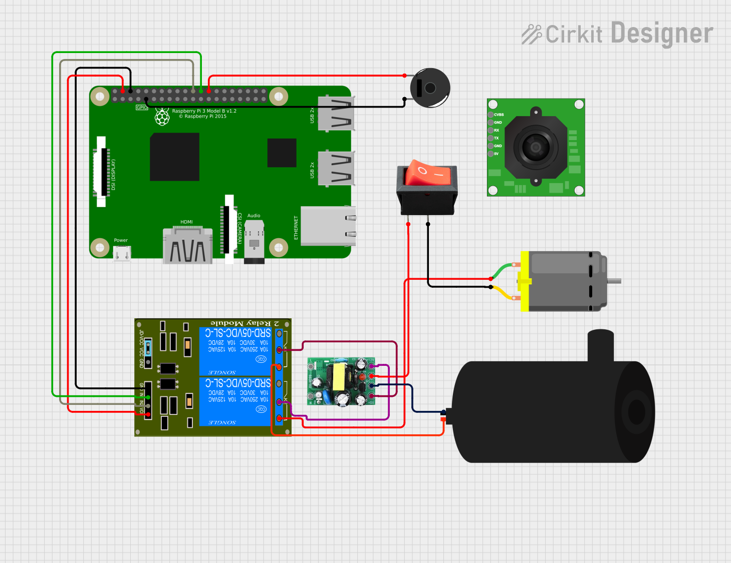
Circuit Documentation
Summary
This document provides a detailed overview of a circuit that includes a Raspberry Pi 3B, a Piezo Buzzer, a DC Motor, an AC-DC PSU board, a 2-Channel Relay, a TTL Serial JPEG Camera, a rocker switch, and a water pump. The circuit is designed to control various components using the Raspberry Pi, with power supplied by the AC-DC PSU board.
Component List
Raspberry Pi 3B
- Description: A single-board computer used to control the circuit.
- Pins: 3v3, GPIO2, GPIO3, GPIO4, GND, GPIO17, GPIO27, GPIO22, 3V3, GPIO10, GPIO9, GPIO11, ID_SD, GPIO5, GPIO6, GPIO13, GPIO19, GPIO26, GPIO21, GPIO20, GPIO16, GPIO12, ID_SC, GPIO7, GPIO8, GPIO25, GPIO24, GPIO23, GPIO18, GPIO15, GPIO14, 5V
Piezo Buzzer
- Description: A buzzer used to produce sound.
- Pins: pin 1, pin 2
DC Motor
- Description: A motor used for mechanical movement.
- Pins: pin 1, pin 2
AC-DC PSU board 220V-5V&12V
- Description: A power supply unit that converts AC to 5V and 12V DC.
- Pins: AC-N, AC-L, +5V, GND, +12V
2-Channel Relay (5V 10A)
- Description: A relay module used to control high-power devices.
- Pins: K1-Off, K1-In, K2-On, K2-In, K1-On, K2-Off, VCC, JD-GND, IN2, IN1, GND
TTL Serial JPEG Camera
- Description: A camera module for capturing images.
- Pins: GND, RX, TX, CVBS, 5V
Rocker Switch
- Description: A switch used to control the power to the DC Motor.
- Pins: output, input
Water Pump
- Description: A pump used for moving water.
- Pins: positive, negative
Wiring Details
Raspberry Pi 3B
- GND is connected to Piezo Buzzer pin 2.
- GPIO7 is connected to Piezo Buzzer pin 1.
- GPIO8 is connected to 2-Channel Relay IN1.
- GPIO25 is connected to 2-Channel Relay IN2.
- GND is connected to 2-Channel Relay GND.
- 5V is connected to 2-Channel Relay VCC.
Piezo Buzzer
- pin 2 is connected to Raspberry Pi GND.
- pin 1 is connected to Raspberry Pi GPIO7.
DC Motor
- pin 1 is connected to 2-Channel Relay K2-On.
- pin 2 is connected to Rocker Switch output.
AC-DC PSU board 220V-5V&12V
- +5V is connected to 2-Channel Relay K1-In.
- GND is connected to Water Pump negative.
- GND is connected to Rocker Switch input.
- +12V is connected to 2-Channel Relay K2-In.
2-Channel Relay (5V 10A)
- IN1 is connected to Raspberry Pi GPIO8.
- IN2 is connected to Raspberry Pi GPIO25.
- GND is connected to Raspberry Pi GND.
- VCC is connected to Raspberry Pi 5V.
- K2-On is connected to DC Motor pin 1.
- K1-In is connected to AC-DC PSU board +5V.
- K2-In is connected to AC-DC PSU board +12V.
- K1-On is connected to Water Pump positive.
Rocker Switch
- output is connected to DC Motor pin 2.
- input is connected to AC-DC PSU board GND.
Water Pump
- negative is connected to AC-DC PSU board GND.
- positive is connected to 2-Channel Relay K1-On.
Code
There is no code provided for the microcontrollers in this circuit.
This document provides a comprehensive overview of the circuit, including a summary, component list, wiring details, and code documentation. Each component is described, and the connections between components are detailed to ensure proper assembly and functionality.