
Circuit Documentation
Summary
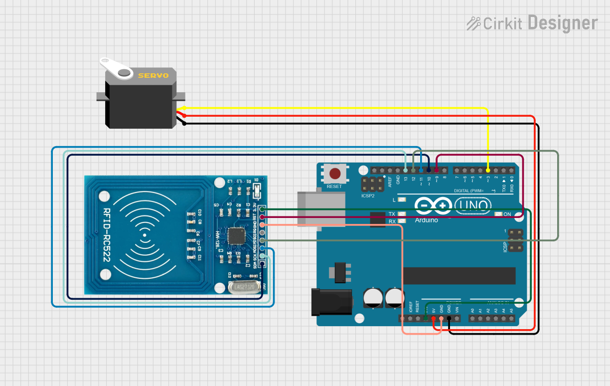
This circuit integrates an Arduino UNO microcontroller with an RFID-RC522 reader and a servo motor. The purpose of the circuit is to read RFID tags and control the servo motor's position based on the tag's data. When an authorized RFID tag is detected, the servo motor is actuated to a specific position, and a green LED and buzzer are activated to indicate successful recognition. If an unauthorized tag is detected, a red LED and buzzer signal the denial of access.
Component List
Arduino UNO
- Description: A microcontroller board based on the ATmega328P.
- Purpose: Acts as the central processing unit for the circuit, controlling the RFID reader, servo motor, and other peripherals.
Servo
- Description: An actuator that can rotate to a specified position.
- Purpose: Moves to a designated angle upon receiving a command from the Arduino, indicating an action such as granting access.
RFID-RC522
- Description: An RFID reader/writer module.
- Purpose: Reads RFID tags and communicates the data to the Arduino for processing.
Wiring Details
Arduino UNO
- 3.3V connected to RFID-RC522 VCC (3.3V)
- 5V connected to Servo VCC
- GND connected to both RFID-RC522 GND and Servo GND
- D13 connected to RFID-RC522 SCK
- D12 connected to RFID-RC522 MISO
- D11 connected to RFID-RC522 MOSI
- D10 connected to RFID-RC522 SDA
- D9 connected to RFID-RC522 RST
- D3 connected to Servo Pulse
Servo
- GND connected to Arduino GND
- VCC connected to Arduino 5V
- Pulse connected to Arduino D3
RFID-RC522
- VCC (3.3V) connected to Arduino 3.3V
- RST connected to Arduino D9
- GND connected to Arduino GND
- IRQ (Not connected)
- MISO connected to Arduino D12
- MOSI connected to Arduino D11
- SCK connected to Arduino D13
- SDA connected to Arduino D10
Documented Code
#include <SPI.h>
#include <MFRC522.h>
#include <Servo.h>

#define SS_PIN 10
#define RST_PIN 9
#define LED_G 5 // Define green LED pin
#define LED_R 4 // Define red LED pin
#define BUZZER 2 // Buzzer pin

MFRC522 mfrc522(SS_PIN, RST_PIN); // Create MFRC522 instance.
Servo myServo; // Define servo name

void setup()
{
  Serial.begin(9600); // Initiate a serial communication
  SPI.begin(); // Initiate SPI bus
  mfrc522.PCD_Init(); // Initiate MFRC522
  myServo.attach(3); // Servo pin
  myServo.write(0); // Servo start position
  pinMode(LED_G, OUTPUT);
  pinMode(LED_R, OUTPUT);
  pinMode(BUZZER, OUTPUT);
  noTone(BUZZER);
  Serial.println("Put your card to the reader...");
  Serial.println();
}

void loop()
{
  // Look for new cards
  if (!mfrc522.PICC_IsNewCardPresent())
  {
    return;
  }
  // Select one of the cards
  if (!mfrc522.PICC_ReadCardSerial())
  {
    return;
  }

  // Show UID on serial monitor
  Serial.print("UID tag :");
  String content = "";

  for (byte i = 0; i < mfrc522.uid.size; i++)
  {
    Serial.print(mfrc522.uid.uidByte[i] < 0x10 ? " 0" : " ");
    Serial.print(mfrc522.uid.uidByte[i], HEX);
    content.concat(String(mfrc522.uid.uidByte[i] < 0x10 ? " 0" : " "));
    content.concat(String(mfrc522.uid.uidByte[i], HEX));
  }

  Serial.println();
  Serial.print("Message : ");
  content.toUpperCase();

  if (content.substring(1) == "6A B2 A6 15") // Change here the UID of the card/cards that you want to give access
  {
    Serial.println("Authorized access");
    Serial.println();
    delay(500);
    digitalWrite(LED_G, HIGH);
    tone(BUZZER, 500);
    delay(300);
    noTone(BUZZER);
    myServo.write(90); // Move the servo to 90 degrees
    delay(2000); // Wait for 2 seconds
    myServo.write(0); // Move the servo back to 0 degrees
    digitalWrite(LED_G, LOW);
  }
  else
  {
    Serial.println(" Access denied");
    digitalWrite(LED_R, HIGH);
    tone(BUZZER, 300);
    delay(1000);
    digitalWrite(LED_R, LOW);
    noTone(BUZZER);
  }
}
This code is designed to run on the Arduino UNO microcontroller. It initializes the RFID-RC522 module and the servo motor, then continuously checks for new RFID tags. When a tag is detected, it reads the UID and checks if it matches a predefined authorized UID. If it matches, it triggers the servo to move, turns on a green LED, and sounds a buzzer. If it does not match, it turns on a red LED and sounds a different tone on the buzzer to indicate denied access.