
ESP32-Controlled Pressure Monitoring System with ADS1115 and Darlington Transistor Switching
View and Edit Project In Cirkit Designer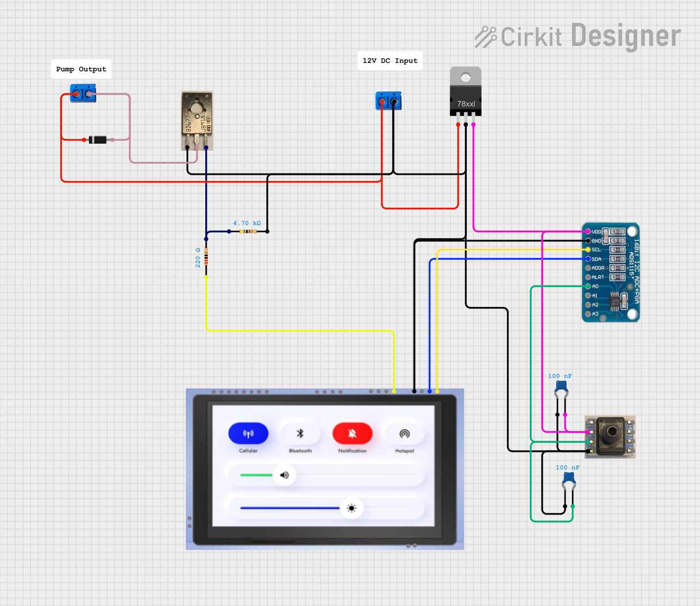
Circuit Documentation
Summary
This document provides a detailed overview of a circuit designed to interface an ADS1115 analog-to-digital converter with an ELECROW ESP32 7" Screen for data acquisition and display. The circuit includes a voltage regulator to provide a stable power supply, a pressure transducer for sensing, resistors for current limiting and pull-up functions, a Darlington transistor for amplification or switching, a diode for directional current flow, and capacitors for noise filtering.
Component List
ADS1115
- Description: 16-bit Analog-to-Digital Converter (ADC)
- Pins: VDD, GND, SCL, SDA, ADDR, ALRT, A0, A1, A2, A3
ELECROW ESP32 7" Screen
- Description: ESP32-based controller with a 7-inch display
- Pins: IO19_I2C_SDA, IO20_I2C_SCL, 3V3, GND, IO38-D, UARTT0_TXD0, UARTT0_RXD0, IO38_D, SDA, SCL, BAT-, BAT+, SPK1, SPK2
Resistor (220 Ohms)
- Description: Current limiting resistor
- Pins: pin1, pin2
- Resistance: 220 Ohms
Resistor (4700 Ohms)
- Description: Pull-up resistor or current limiting
- Pins: pin1, pin2
- Resistance: 4700 Ohms
Voltage Regulator
- Description: Provides a stable voltage output
- Pins: IN, GND, OUT
BD677 NPN Darlington Transistor
- Description: Amplification or switching applications
- Pins: (1) Base, (2) Collector, (3) Emitter
Pressure Transducer
- Description: Sensor for measuring pressure
- Pins: NC, VDD, Vout, GND
Diode
- Description: Allows current to flow in one direction
- Pins: cathode, anode
Ceramic Capacitor (0.1 µF)
- Description: Noise filtering capacitor
- Pins: pin0, pin1
- Capacitance: 0.1 µF
Terminal PCB 2 Pin
- Description: Connection point for external wiring
- Pins: Pin A, Pin B
Wiring Details
ADS1115
- VDD connected to Voltage Regulator OUT
- GND connected to system ground
- SCL connected to ELECROW ESP32 SCL
- SDA connected to ELECROW ESP32 SDA
- A0 connected to Pressure Transducer Vout
ELECROW ESP32 7" Screen
- IO19_I2C_SDA connected to ADS1115 SDA
- IO20_I2C_SCL connected to ADS1115 SCL
- GND connected to system ground
- IO38_D connected to 220 Ohm Resistor pin1
Resistor (220 Ohms)
- pin1 connected to ELECROW ESP32 IO38_D
- pin2 connected to system ground
Resistor (4700 Ohms)
- pin1 connected to BD677 NPN Darlington Transistor Base
- pin2 connected to system ground
Voltage Regulator
- IN connected to Terminal PCB 2 Pin Pin A and Diode cathode
- GND connected to system ground
- OUT connected to ADS1115 VDD
BD677 NPN Darlington Transistor
- Base connected to 4700 Ohm Resistor pin1
- Collector connected to Diode anode and Terminal PCB 2 Pin Pin B
- Emitter connected to system ground
Pressure Transducer
- VDD connected to ADS1115 VDD
- Vout connected to ADS1115 A0
- GND connected to system ground
Diode
- cathode connected to Voltage Regulator IN
- anode connected to BD677 NPN Darlington Transistor Collector
Ceramic Capacitor (0.1 µF)
- pin0 connected to system ground
- pin1 connected to ADS1115 VDD and Pressure Transducer VDD
Terminal PCB 2 Pin
- Pin A connected to Voltage Regulator IN
- Pin B connected to system ground
Documented Code
ELECROW ESP32 7" Screen Microcontroller Code (sketch.ino)
void setup() {
  // put your setup code here, to run once:

}

void loop() {
  // put your main code here, to run repeatedly:

}
This code is a template for the ESP32 microcontroller. The setup() function is called once when the microcontroller is powered on or reset. The loop() function is called repeatedly and contains the main logic of the program. The user will need to fill in the logic for initializing the I2C communication with the ADS1115 and handling the display on the 7" screen, as well as reading the pressure transducer data through the ADC and displaying it.