
Circuit Documentation
Summary
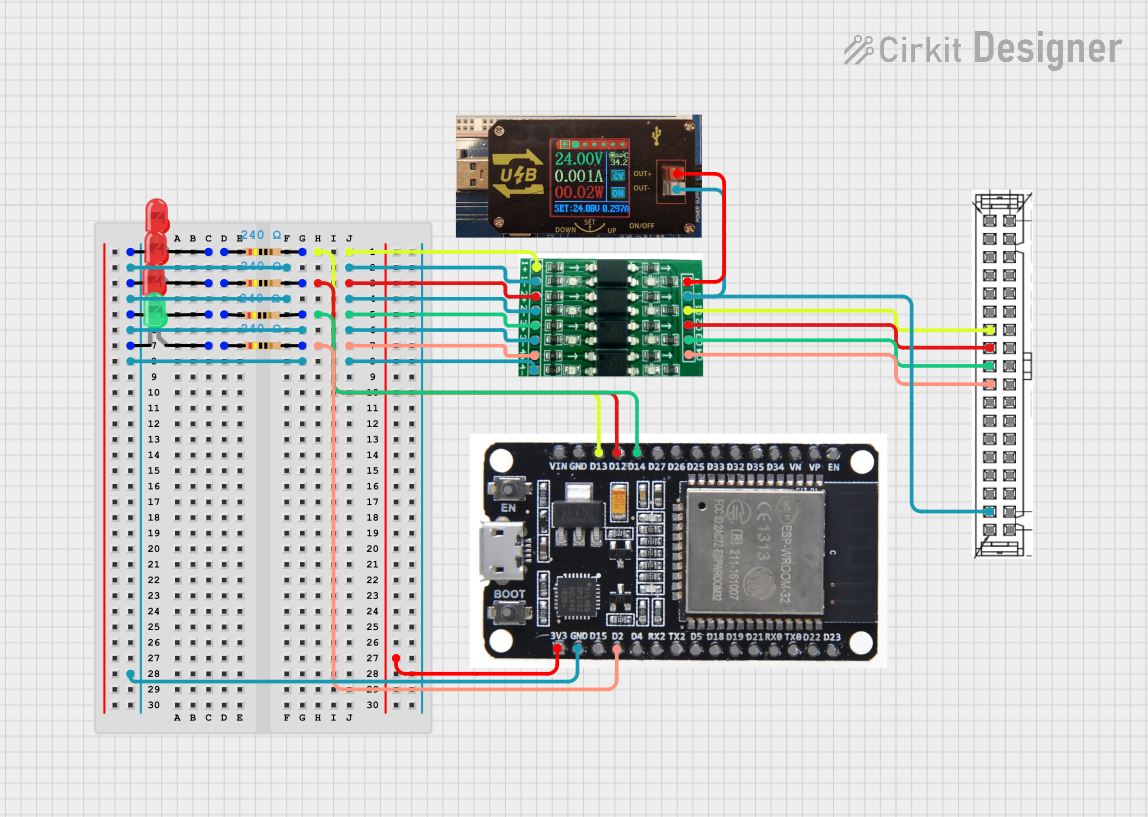
This circuit consists of multiple LEDs (both red and green), resistors, an ESP32 microcontroller, a logic level converter, a 40-pin connector, and a USB power supply. The circuit is designed to control the LEDs using the ESP32 microcontroller, with the logic level converter ensuring proper voltage levels. The USB power supply provides the necessary power to the circuit.
Component List
LED: Two Pin (red)
- Pins: cathode, anode
- Description: Red LED used for visual indication.
LED: Two Pin (green)
- Pins: cathode, anode
- Description: Green LED used for visual indication.
Resistor
- Pins: pin1, pin2
- Description: Resistor used to limit current.
- Properties:
- Resistance: 240 Ohms
ESP32
- Pins: EN, VP, VN, D34, D35, D32, D33, D25, D26, D27, D14, D12, D13, GND, VIN, 3V3, D15, D2, D4, RX2, TX2, D5, D18, D19, D21, RX0, TX0, D22, D23, BOOT
- Description: Microcontroller used to control the LEDs.
Logic Level Converter
- Pins: 1+, 1-, 2+, 2-, 3+, 3-, 4+, 4-, 04, 03, 02, 01, G, V
- Description: Used to convert voltage levels between the ESP32 and other components.
40-Pin Connector
- Pins: General purpose input 0, General purpose input 1, General purpose input 2, General purpose input 3, General purpose input 4, General purpose input 5, General purpose input 6, General purpose input 8, General purpose input 9, General purpose input 10, General purpose input 11, General purpose input 12, General purpose input 13, General purpose input 14, General purpose input 7, General purpose input 15, Com for input pins 5c-20C, 0V for output pins 5D-20D, General purpose output 0, General purpose output 1, General purpose output 2, General purpose output 3, General purpose output 4, General purpose output 5, General purpose output 6, General purpose output 7, General purpose output 8, General purpose output 9, General purpose output 10, General purpose output 11, General purpose output 12, General purpose output 13, General purpose output 14, General purpose output 15, No Connection (NC), 24V for output pins 5D-20D
- Description: Connector used for interfacing with external devices.
USB Power Supply
- Pins: Out+, Out-
- Description: Provides power to the circuit.
Wiring Details
LED: Two Pin (red)
- Anode connected to pin1 of a Resistor.
- Cathode connected to:
- 1- of Logic Level Converter
- 2- of Logic Level Converter
- 3- of Logic Level Converter
- 4- of Logic Level Converter
- GND of ESP32
LED: Two Pin (green)
- Anode connected to pin1 of a Resistor.
- Cathode connected to:
- 1- of Logic Level Converter
- 2- of Logic Level Converter
- 3- of Logic Level Converter
- 4- of Logic Level Converter
- GND of ESP32
Resistor
- Pin1 connected to the anode of an LED.
- Pin2 connected to:
- D13 of ESP32 and 1+ of Logic Level Converter
- D12 of ESP32 and 2+ of Logic Level Converter
- D14 of ESP32 and 3+ of Logic Level Converter
- D2 of ESP32 and 4+ of Logic Level Converter
ESP32
- D13 connected to pin2 of a Resistor and 1+ of Logic Level Converter.
- D12 connected to pin2 of a Resistor and 2+ of Logic Level Converter.
- D14 connected to pin2 of a Resistor and 3+ of Logic Level Converter.
- D2 connected to pin2 of a Resistor and 4+ of Logic Level Converter.
- GND connected to:
- 1- of Logic Level Converter
- 2- of Logic Level Converter
- 3- of Logic Level Converter
- 4- of Logic Level Converter
- 3V3 connected to the power supply.
Logic Level Converter
- 1+ connected to pin2 of a Resistor and D13 of ESP32.
- 1- connected to the cathode of LEDs and GND of ESP32.
- 2+ connected to pin2 of a Resistor and D12 of ESP32.
- 2- connected to the cathode of LEDs and GND of ESP32.
- 3+ connected to pin2 of a Resistor and D14 of ESP32.
- 3- connected to the cathode of LEDs and GND of ESP32.
- 4+ connected to pin2 of a Resistor and D2 of ESP32.
- 4- connected to the cathode of LEDs and GND of ESP32.
- 04 connected to General purpose input 9 of 40-Pin Connector.
- 03 connected to General purpose input 8 of 40-Pin Connector.
- 02 connected to General purpose input 7 of 40-Pin Connector.
- 01 connected to General purpose input 6 of 40-Pin Connector.
- G connected to Out- of USB Power Supply and Com for input pins 5c-20C of 40-Pin Connector.
- V connected to Out+ of USB Power Supply.
40-Pin Connector
- General purpose input 9 connected to 04 of Logic Level Converter.
- General purpose input 8 connected to 03 of Logic Level Converter.
- General purpose input 7 connected to 02 of Logic Level Converter.
- General purpose input 6 connected to 01 of Logic Level Converter.
- Com for input pins 5c-20C connected to Out- of USB Power Supply and G of Logic Level Converter.
USB Power Supply
- Out+ connected to V of Logic Level Converter.
- Out- connected to G of Logic Level Converter and Com for input pins 5c-20C of 40-Pin Connector.
Code
No code is provided for this circuit.