
Arduino UNO R4 WiFi-Controlled Stepper Motor with Limit Switches and LED Indicators
View and Edit Project In Cirkit Designer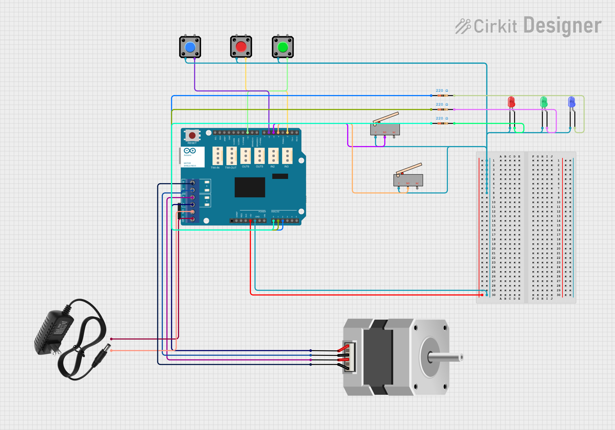
Circuit Documentation
Summary
This circuit is designed to control a bipolar stepper motor using an Arduino UNO R4 WiFi and an Arduino Motor Shield (Rev3). The circuit includes pushbuttons and limit switches for user input, as well as red, green, and blue LEDs to provide visual feedback. The stepper motor's movement can be controlled in terms of direction and steps, with limit switches providing boundary conditions. The circuit is powered by a 12V power supply, and resistors are used to limit current to the LEDs.
Component List
- Arduino UNO R4 WiFi: A microcontroller board based on the ATmega328, which includes WiFi capabilities. It is used as the central controller for the circuit.
- Arduino Motor Shield (Rev3): A shield that fits on top of the Arduino UNO and provides the ability to drive DC and stepper motors with dedicated power and control logic.
- Stepper Motor (Bipolar): A bipolar stepper motor that is controlled by the motor shield to perform precise movements.
- 12V Power Supply: Provides the necessary voltage and current to power the motor and the motor shield.
- Pushbuttons (3x): User input devices that allow for interaction with the circuit, such as starting or stopping the motor and toggling LED states.
- Limit Switches (2x): Mechanical switches that limit the range of the stepper motor's movement and prevent it from overextending.
- LEDs (Red, Green, Blue): Visual indicators that show the status of the circuit or user interactions.
- Resistors (220 Ohms, 3x): Limit the current flowing through the LEDs to prevent damage.
Wiring Details
Arduino UNO R4 WiFi
Digital Pins:
- D2: Connected to a pushbutton.
- D4: Connected to a limit switch (NO contact).
- D5: Connected to another limit switch (NO contact).
- D6: Connected to a pushbutton.
- D10: Connected to a pushbutton.
Analog Pins:
- A0: Connected to a red LED through a 220 Ohm resistor.
- A1: Connected to a green LED through a 220 Ohm resistor.
- A2: Connected to a blue LED through a 220 Ohm resistor.
Power Pins:
- 5V and GND: Power supply for the motor shield and common ground reference.
Arduino Motor Shield (Rev3)
- Motor Control Pins:
- A+, A-, B+, B-: Connected to the corresponding wires of the bipolar stepper motor.
- VMOT: Connected to the positive terminal of the 12V power supply.
- GND: Connected to the negative terminal of the 12V power supply and common ground with the Arduino UNO.
Stepper Motor (Bipolar)
- Motor Wires:
- A, B, C, D: Connected to the motor control pins on the motor shield (A+, A-, B+, B-).
Pushbuttons
- Common Pins:
- One side of each pushbutton is connected to a common ground net that includes the GND pin of the motor shield and the cathodes of all LEDs.
- Individual Pins:
- Each pushbutton has another pin connected to a specific digital pin on the Arduino UNO for input detection.
Limit Switches
- Common Pin:
- The common (C) pins of both limit switches are connected to the common ground net.
- Normally Open (NO) Contacts:
- Each limit switch's NO contact is connected to a specific digital pin on the Arduino UNO for input detection.
LEDs
- Cathodes:
- The cathodes of all LEDs are connected to the common ground net.
- Anodes:
- Each LED's anode is connected to an analog pin on the Arduino UNO through a 220 Ohm resistor.
Resistors
- Connections:
- Each resistor is connected in series between an LED anode and an Arduino UNO analog pin.
Documented Code
#include "Stepper.h"

// Define number of steps per revolution:
const int stepsPerRevolution = 200;

// Define button pins:
const int redButtonPin = 2;
const int greenButtonPin = 10;
const int blueButtonPin = 6;

// Define limit switch pins:
const int forwardLimitSwitchPin = 5;
const int backwardLimitSwitchPin = 4;

// Define LED pins:
const int redLEDPin = A0;
const int greenLEDPin = A1;
const int blueLEDPin = A2;

// Give the motor control pins names:
#define pwmA 3
#define pwmB 11
#define brakeA 9
#define brakeB 8
#define dirA 12
#define dirB 13

// Initialize the stepper library on the motor shield:
Stepper myStepper = Stepper(stepsPerRevolution, dirA, dirB);

// Variables to keep track of the motor state:
bool motorDirection = true; // true for forward (clockwise), false for backward (counter-clockwise)

// Variables to store previous states
int prevRedButtonState = LOW; // Inverted logic
int prevGreenButtonState = LOW; // Inverted logic
int prevBlueButtonState = LOW; // Inverted logic
int prevForwardLimitSwitchState = HIGH;
int prevBackwardLimitSwitchState = HIGH;

void setup() {
  Serial.begin(9600); // Initialize serial communication for debugging

  // Set the PWM and brake pins so that the direction pins can be used to control the motor:
  pinMode(pwmA, OUTPUT);
  pinMode(pwmB, OUTPUT);
  pinMode(brakeA, OUTPUT);
  pinMode(brakeB, OUTPUT);

  digitalWrite(pwmA, HIGH);
  digitalWrite(pwmB, HIGH);
  digitalWrite(brakeA, LOW);
  digitalWrite(brakeB, LOW);

  // Set the motor speed (RPMs):
  myStepper.setSpeed(80);

  // Set button pins as inputs with internal pull-up resistors:
  pinMode(redButtonPin, INPUT_PULLUP);
  pinMode(greenButtonPin, INPUT_PULLUP);
  pinMode(blueButtonPin, INPUT_PULLUP);

  // Set limit switch pins as inputs with internal pull-up resistors:
  pinMode(forwardLimitSwitchPin, INPUT_PULLUP);
  pinMode(backwardLimitSwitchPin, INPUT_PULLUP);

  // Set LED pins as outputs:
  pinMode(redLEDPin, OUTPUT);
  pinMode(greenLEDPin, OUTPUT);
  pinMode(blueLEDPin, OUTPUT);

  // Initialize LEDs to be off:
  digitalWrite(redLEDPin, LOW);
  digitalWrite(greenLEDPin, LOW);
  digitalWrite(blueLEDPin, LOW);
}

void loop() {
  // Read the current state of the buttons and limit switches
  int currentRedButtonState = !digitalRead(redButtonPin); // Inverted logic
  int currentGreenButtonState = !digitalRead(greenButtonPin); // Inverted logic
  int currentBlueButtonState = !digitalRead(blueButtonPin); // Inverted logic
  int currentForwardLimitSwitchState = digitalRead(forwardLimitSwitchPin);
  int currentBackwardLimitSwitchState = digitalRead(backwardLimitSwitchPin);

  // Debugging: Print the state of the buttons
  Serial.print("Red Button State: ");
  Serial.println(currentRedButtonState);
  Serial.print("Green Button State: ");
  Serial.println(currentGreenButtonState);
  Serial.print("Blue Button State: ");
  Serial.println(currentBlueButtonState);

  // Control LEDs based on button states:
  digitalWrite(redLEDPin, currentRedButtonState == HIGH ? HIGH : LOW); // Inverted logic
  digitalWrite(greenLEDPin, currentGreenButtonState == HIGH ? HIGH : LOW); // Inverted logic
  digitalWrite(blueLEDPin, currentBlueButtonState == HIGH ? HIGH : LOW); // Inverted logic

  // Check the state of the red button to control direction:
  if (currentRedButtonState == HIGH && prevRedButtonState == LOW) { // Inverted logic
    motorDirection = !motorDirection; // Toggle motor direction
    Serial.println("Red button pressed, toggling motor direction");
    if (motorDirection) {
      Serial.println("Motor direction: Forward (Clockwise)");
    } else {
      Serial.println("Motor direction: Backward (Counter-Clockwise)");
    }
    delay(100); // Increase debounce delay to 100ms
  }

  // Check the state of the green button to enable/disable the motor:
  if (currentGreenButtonState == HIGH && prevGreenButtonState == LOW) { // Inverted logic
    // Single press detected, turn the motor one revolution
    if (motorDirection && currentForwardLimitSwitchState == HIGH) {
      myStepper.step(stepsPerRevolution); // Step one revolution forward (clockwise)
    } else if (!motorDirection && currentBackwardLimitSwitchState == HIGH) {
      myStepper.step(-stepsPerRevolution); // Step one revolution backward (counter-clockwise)
    }
    delay(100); // Increase debounce delay to 100ms
  }

  // Check if the green button is pressed while the blue button is being held
  if (currentGreenButtonState == HIGH && currentBlueButtonState == HIGH) { // Inverted logic
    // Continue turning the