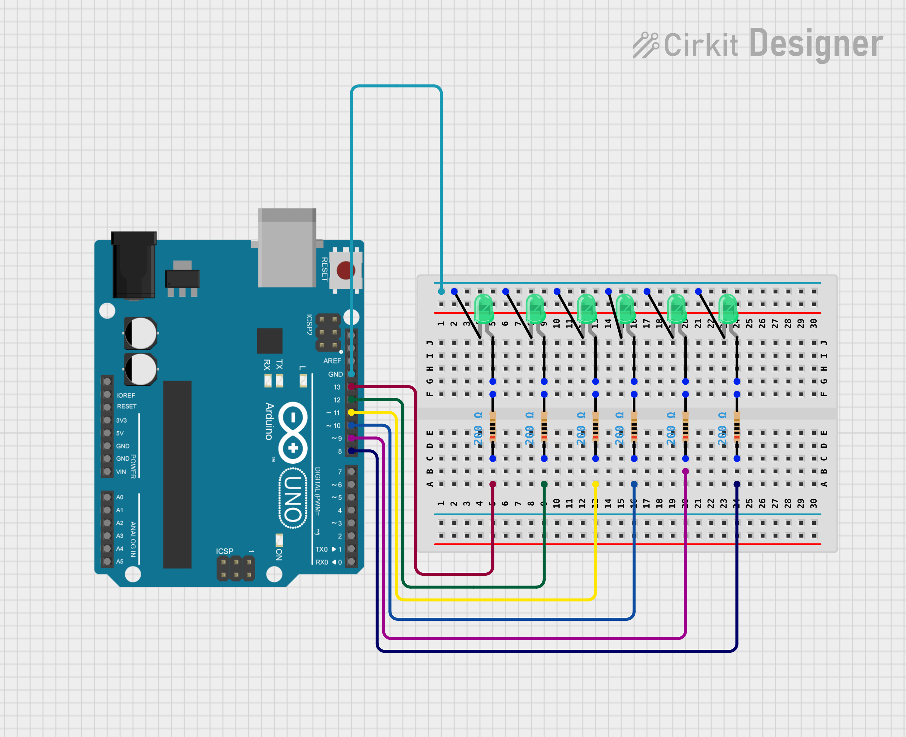
Arduino UNO Controlled Blinking LED Array

Circuit Documentation
Summary of the Circuit
This circuit is designed around an Arduino UNO microcontroller and is used to control six green LEDs. Each LED is connected to one of the digital pins (D8 to D13) on the Arduino through a 200 Ohm resistor. The purpose of the resistors is to limit the current flowing through the LEDs to prevent damage. The circuit includes a simple control mechanism implemented in the Arduino's firmware, which turns the LEDs on and off in a sequential manner. Additionally, the Arduino is programmed to initialize serial communication at 9600 baud and print a message to the serial monitor upon setup.
Component List
Microcontroller
- Arduino UNO: A microcontroller board based on the ATmega328P. It has 14 digital input/output pins, 6 analog inputs, a USB connection, a power jack, an ICSP header, and a reset button.
LEDs
- LED: Two Pin (green): A basic green light-emitting diode with two pins, an anode, and a cathode.
Resistors
- Resistor: A passive two-terminal electrical component that implements electrical resistance as a circuit element. In this circuit, all resistors have a value of 200 Ohms.
Wiring Details
Arduino UNO
- Digital Pins (D8 to D13): Each pin is connected to the anode of a green LED through a 200 Ohm resistor.
- GND: Connected to the cathodes of all six green LEDs, providing a common ground reference.
LEDs
- Green LED 1: Anode connected to D13 through a resistor, cathode connected to GND.
- Green LED 2: Anode connected to D12 through a resistor, cathode connected to GND.
- Green LED 3: Anode connected to D11 through a resistor, cathode connected to GND.
- Green LED 4: Anode connected to D10 through a resistor, cathode connected to GND.
- Green LED 5: Anode connected to D9 through a resistor, cathode connected to GND.
- Green LED 6: Anode connected to D8 through a resistor, cathode connected to GND.
Resistors
- Resistor 1: One pin connected to D13, the other pin to the anode of LED 1.
- Resistor 2: One pin connected to D12, the other pin to the anode of LED 2.
- Resistor 3: One pin connected to D11, the other pin to the anode of LED 3.
- Resistor 4: One pin connected to D10, the other pin to the anode of LED 4.
- Resistor 5: One pin connected to D9, the other pin to the anode of LED 5.
- Resistor 6: One pin connected to D8, the other pin to the anode of LED 6.
Documented Code
/*
 * This Arduino Sketch controls six green LEDs connected to digital pins 8 to 13.
 * It uses DDRB and PORTB registers for efficient pin control.
 * Additionally, it initializes serial communication and prints a message.
 */

void setup() {
  // Set pins 8 to 13 as outputs using DDRB register
  DDRB = B00111111;
  // Initialize serial communication at 9600 baud
  Serial.begin(9600);
  // Print a message to the serial monitor
  Serial.println("LED control initialized.");
}

void loop() {
  // Print the state of pins 8 to 13 to the serial monitor
  Serial.println(PINB,BIN);
  // Turn on LEDs connected to pins 8 to 13
  PORTB = B00111111;
  delay(1000); // Wait for 1 second
  // Turn off LEDs connected to pins 8 to 13
  PORTB = B00000000;
  delay(1000); // Wait for 1 second
}
The code is written for the Arduino UNO and is contained in a sketch file. It initializes the digital pins 8 to 13 as outputs and sets up serial communication. In the main loop, it toggles the LEDs on and off every second and prints the state of the pins to the serial monitor.