Cirkit Designer
Your all-in-one circuit design IDE
Home /
Project Documentation
Arduino UNO and ESP8266 Wi-Fi Controlled Relay with LCD Display
Circuit Documentation
Summary
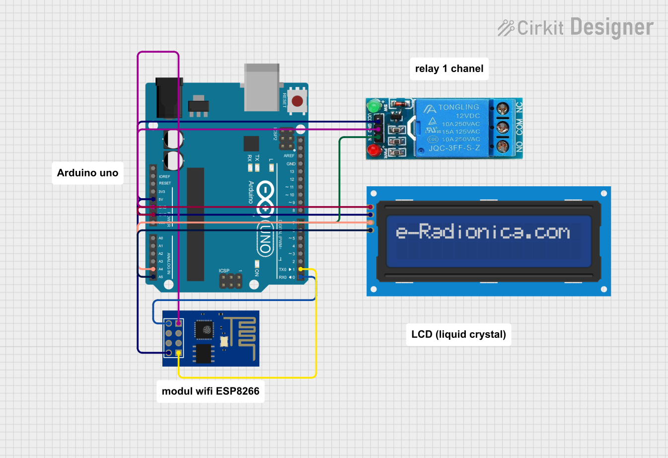
This circuit integrates an Arduino UNO microcontroller, an ESP8266 ESP-01 WiFi module, a 12V single-channel relay, and a 16x2 I2C LCD screen. The Arduino UNO serves as the central controller, interfacing with the WiFi module for network communication, the relay for switching operations, and the LCD screen for display purposes.
Component List
Arduino UNO
- Description: A microcontroller board based on the ATmega328P.
- Pins: UNUSED, IOREF, Reset, 3.3V, 5V, GND, Vin, A0, A1, A2, A3, A4, A5, SCL, SDA, AREF, D13, D12, D11, D10, D9, D8, D7, D6, D5, D4, D3, D2, D1, D0
ESP8266 ESP-01 WiFi Module
- Description: A WiFi module based on the ESP8266 SoC.
- Pins: TXD, CH_PD, RST, VCC, GND, GPIO_2, GPIO_0, RXD
12V SINGLE CHANNEL RELAY
- Description: A relay module for switching high voltage devices.
- Pins: NC, COM, NO, IN, GND, VCC
LCD screen 16x2 I2C
- Description: A 16x2 character LCD display with I2C interface.
- Pins: SCL, SDA, VCC, GND
Comment
- Description: Placeholder for comments in the circuit.
- Pins: None
Wiring Details
Arduino UNO
- 5V: Connected to VCC of the 12V SINGLE CHANNEL RELAY, ESP8266 ESP-01 WiFi Module, and LCD screen 16x2 I2C.
- GND: Connected to GND of the 12V SINGLE CHANNEL RELAY, ESP8266 ESP-01 WiFi Module, and LCD screen 16x2 I2C.
- A4: Connected to SDA of the LCD screen 16x2 I2C.
- A5: Connected to SCL of the LCD screen 16x2 I2C.
- D7: Connected to IN of the 12V SINGLE CHANNEL RELAY.
- D1: Connected to RXD of the ESP8266 ESP-01 WiFi Module.
- D0: Connected to TXD of the ESP8266 ESP-01 WiFi Module.
ESP8266 ESP-01 WiFi Module
- VCC: Connected to 5V of the Arduino UNO.
- GND: Connected to GND of the Arduino UNO.
- RXD: Connected to D1 of the Arduino UNO.
- TXD: Connected to D0 of the Arduino UNO.
12V SINGLE CHANNEL RELAY
- VCC: Connected to 5V of the Arduino UNO.
- GND: Connected to GND of the Arduino UNO.
- IN: Connected to D7 of the Arduino UNO.
LCD screen 16x2 I2C
- VCC: Connected to 5V of the Arduino UNO.
- GND: Connected to GND of the Arduino UNO.
- SDA: Connected to A4 of the Arduino UNO.
- SCL: Connected to A5 of the Arduino UNO.
Documented Code
Arduino UNO Code (sketch.ino)
void setup() {
  // put your setup code here, to run once:

}

void loop() {
  // put your main code here, to run repeatedly:

}
Documentation (documentation.txt)
This documentation provides a comprehensive overview of the circuit, detailing the components used, their connections, and the code running on the Arduino UNO microcontroller.