Cirkit Designer
Your all-in-one circuit design IDE
Home /
Project Documentation
ESP32-Controlled Bluetooth Robotic Vehicle with MT3608 Boost Converters and L298N Motor Drivers

Circuit Documentation
Summary
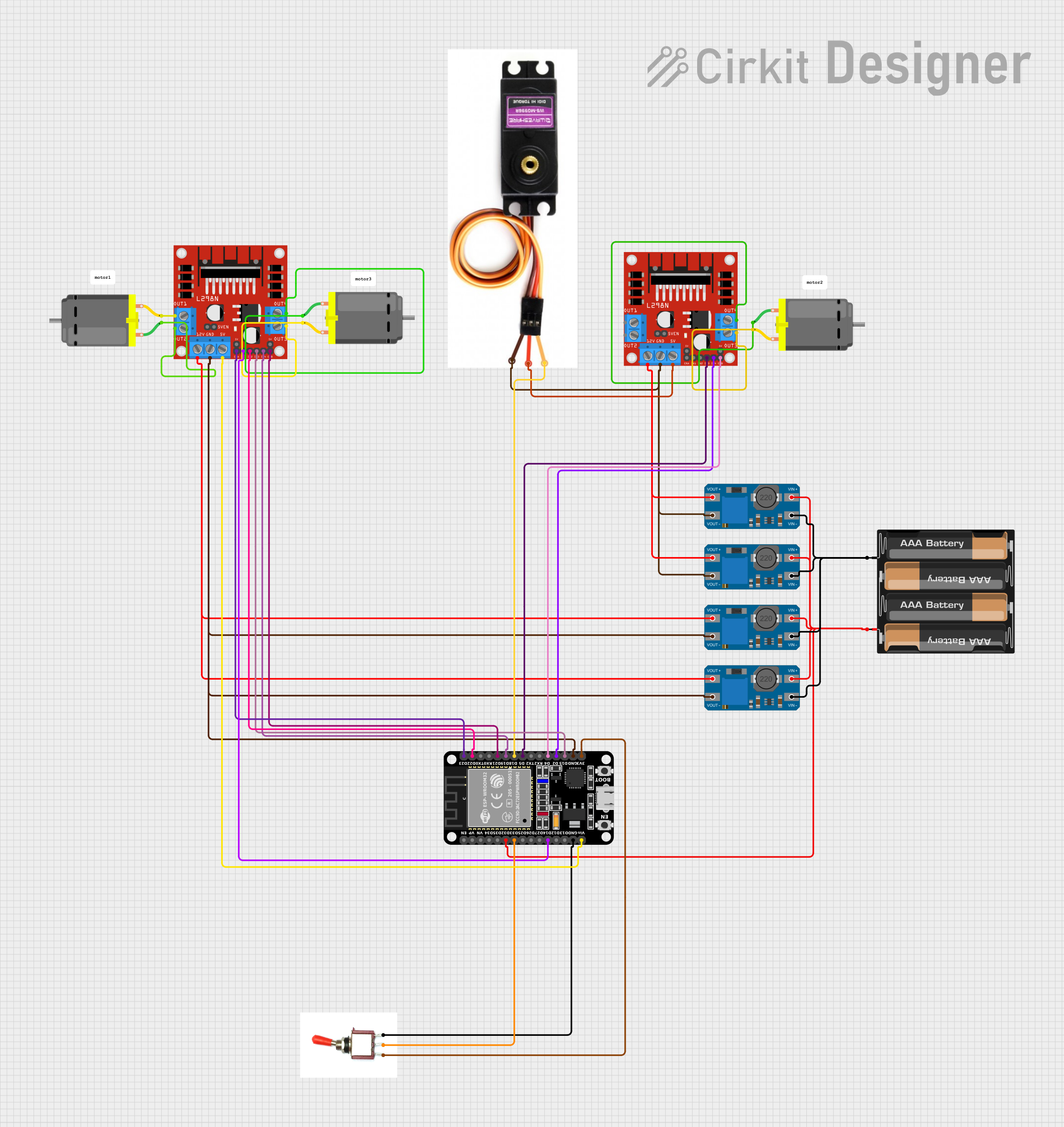
This circuit is designed to control a set of DC motors and a servo motor using an ESP32 microcontroller. The ESP32 is interfaced with an L298N DC motor driver to control the direction and speed of the motors. The circuit also includes MT3608 step-up converters to boost the voltage from a 4 x AAA battery mount to the required level for the motors and the motor driver. A toggle switch is used to control the power flow to the ESP32. The ESP32 is programmed to receive Bluetooth commands to control the movement of the motors, enabling wireless control of the system.
Component List
Microcontroller
- ESP32 (30 pin): A microcontroller with Bluetooth capability for wireless communication and control of the motors.
Power Management
- MT3608: A DC-DC step-up converter used to boost the voltage from the battery to the required level for the motor driver and motors.
- 4 x AAA Battery Mount: Provides the power source for the circuit.
Motor Control
- L298N DC Motor Driver: An H-bridge motor driver that allows for the control of two DC motors' speed and direction.
- DC Motor: The actuators in the circuit that are controlled by the motor driver.
- MG996R: A servo motor used for precise control of mechanical components.
User Interface
- Toggle Switch: A switch to control the power supply to the ESP32 microcontroller.
Miscellaneous
- Comment: Placeholder for additional notes or comments in the circuit design.
Wiring Details
ESP32 (30 pin)
EN,VP,VN,D34,D35,D25,D26,D27,TX0,RX0,D23,TX2,RX2,D4,D2,3V3: Not connected.D32: Connected to the positive terminal of the 4 x AAA Battery Mount.D33: Connected to the signal pin of the Toggle Switch.D14,D22,D21,D19,D18,D5,D15: Connected to various control pins of the L298N DC Motor Drivers.GND: Common ground with the MT3608s, L298N DC Motor Drivers, and MG996R.Vin: Connected to the 5V output of the L298N DC Motor Driver.
MT3608
VIN+: Connected to the positive terminal of the 4 x AAA Battery Mount.VIN-: Connected to the negative terminal of the 4 x AAA Battery Mount.VOUT+: Connected to the 12V input of the L298N DC Motor Drivers.VOUT-: Common ground with the ESP32 and L298N DC Motor Drivers.
L298N DC Motor Driver
OUT1,OUT2,OUT3,OUT4: Connected to the respective pins of the DC Motors.12V: Connected to the VOUT+ of the MT3608s.GND: Common ground with the ESP32, MT3608s, and MG996R.5V: Connected to the Vcc of the MG996R.5V-ENA-JMP-I,5V-ENA-JMP-O,+5V-J1,+5V-J2: Not connected.ENA,IN1,IN2,IN3,IN4,ENB: Connected to various control pins of the ESP32.
MG996R
Signal Line: Connected to the D18 pin of the ESP32.Vcc: Connected to the 5V output of the L298N DC Motor Driver.GND: Common ground with the ESP32 and L298N DC Motor Drivers.
4 x AAA Battery Mount
+: Connected to the VIN+ of the MT3608s and D32 of the ESP32.-: Connected to the VIN- of the MT3608s.
DC Motor
pin 1,pin 2: Connected to the respective output pins of the L298N DC Motor Drivers.
Toggle Switch
Vcc: Connected to the 3V3 pin of the ESP32.Sig: Connected to the D33 pin of the ESP32.Gnd: Connected to the GND pin of the ESP32.
Documented Code
#include "BluetoothSerial.h"

#define motor1Pin1  14
#define motor1Pin2  22
#define motor1Enable  23
#define motor2Pin1  5
#define motor2Pin2  2
#define motor2Enable  4
#define motor3Pin1  15
#define motor3Pin2  19
#define motor3Enable  21
const int canalPWM = 0; // Canal PWM
const int freq = 5000;  // Frequência do PWM
const int resolucao = 8; //resolução do PWM

BluetoothSerial SeriallBT;
char comando; //criação de uma variável para comandar o carro através do bluettoth

void setup() {
    // Inicializando o Bluetooth
    Serial.begin(9600);
    SeriallBT.begin("Carrinho");

    // Configura o canal PWM
    ledcSetup(canalPWM, freq, resolucao);
    // Anexa o pino ao canal PWM (define pinoPWM or use the correct pin)
    // ledcAttachPin(pinoPWM, canalPWM);

    // Inicializando pinos como output
    pinMode(motor1Pin1, OUTPUT);
    pinMode(motor1Pin2, OUTPUT);
    pinMode(motor1Enable, OUTPUT);
    pinMode(motor2Pin1, OUTPUT);
    pinMode(motor2Pin2, OUTPUT);
    pinMode(motor2Enable, OUTPUT);
    pinMode(motor3Pin1, OUTPUT);
    pinMode(motor3Pin2, OUTPUT);
    pinMode(motor3Enable, OUTPUT);
}

void loop() {
    if (SeriallBT.available()) {
        comando = SeriallBT.read();
    }

    switch (comando) {
        case 'F': // Mover frente
            MoveFoward();
            break;
        case 'B': // Mover trás
            MoveBackward();
            break;
        case 'G': // Frente esquerda
            MoveFowardLeft();
            break;
        case 'I': // Frente direita
            MoveFowardRight();
            break;
        case 'H': // Mover trás esquerda
            MoveBackwardLeft();
            break;
        case 'J': // Mover trás direita
            MoveBackwardRight();
            break;
    }
}

void MoveFoward() {
    analogWrite(motor2Enable, 255);
    analogWrite(motor3Enable, 255);
    digitalWrite(motor1Pin1, LOW);
    digitalWrite(motor1Pin2, LOW);
    digitalWrite(motor2Pin1, LOW);
    digitalWrite(motor2Pin2, HIGH); // Sentido antihorário 1
    digitalWrite(motor3Pin1, HIGH); // Sentido horário 2
    digitalWrite(motor3Pin2, LOW);
}

void MoveBackward() {
    analogWrite(motor2Enable, 255);
    analogWrite(motor3Enable, 255);
    digitalWrite(motor1Pin1, LOW);
    digitalWrite(motor1Pin2, LOW);
    digitalWrite(motor2Pin1, HIGH); //sentido horário 1
    digitalWrite(motor2Pin2, LOW);
    digitalWrite(motor3Pin1, LOW);
    digitalWrite(motor3Pin2, HIGH); // Sentido antihoráro 2
}

void MoveFowardLeft() {
    analogWrite(motor2Enable, 255);
    analogWrite(motor1Enable, 255);
    digitalWrite(motor1Pin1, HIGH); // Sentido horário 1
    digitalWrite(motor1Pin2, LOW);
    digitalWrite(motor2Pin1, LOW);
    digitalWrite(motor2Pin2, HIGH); // Sentido antihorário 2
    digitalWrite(motor3Pin1, LOW);
    digitalWrite(motor3Pin2, LOW);
}

void MoveFowardRight() {
    analogWrite(motor3Enable, 255);
    analogWrite(motor1Enable, 255);
    digitalWrite(motor1Pin1, LOW);
    digitalWrite(motor1Pin2, HIGH);// Sentido antihorário
    digitalWrite(motor2Pin1, LOW);
    digitalWrite(motor2Pin2, LOW);
    digitalWrite(motor3Pin1, HIGH); // Sentido horário
    digitalWrite(motor3Pin2, LOW);
}

void MoveBackwardLeft() {
    analogWrite(motor3Enable, 255);
    analogWrite(motor1Enable, 255);
    digitalWrite(motor1Pin1, HIGH); // Sentido horário
    digitalWrite(motor1Pin2, LOW);
    digitalWrite(motor2Pin1, LOW);
    digitalWrite(motor2Pin2, LOW);
    digitalWrite(motor3Pin1, LOW);
    digitalWrite(motor3Pin2, HIGH); // Sentido antihorário
}

void MoveBackward