
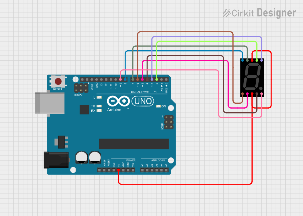
Circuit Documentation
Summary
This circuit utilizes an Arduino UNO microcontroller to control a Seven Segment Display. The display is used to show digits from 0 to 9 in a sequential manner, with each segment of the display being controlled by the microcontroller's digital output pins. The circuit is designed to demonstrate basic control of a common anode seven-segment display.
Component List
Arduino UNO
- Description: A microcontroller board based on the ATmega328P. It is used for programming and controlling the circuit.
- Purpose: Acts as the main control unit for the circuit, sending signals to the Seven Segment Display to control which digits are shown.
Seven Segment Display
- Description: A display device that can show decimal numbers using seven individual segments.
- Purpose: Displays the digits from 0 to 9 based on the signals received from the Arduino UNO.
Wiring Details
Arduino UNO
5V: Connected to COM.2 of the Seven Segment Display (Power supply for the display).
D9: Connected to DP of the Seven Segment Display (Controls the decimal point segment).
D8: Connected to G of the Seven Segment Display (Controls the segment G).
D7: Connected to F of the Seven Segment Display (Controls the segment F).
D6: Connected to E of the Seven Segment Display (Controls the segment E).
D5: Connected to D of the Seven Segment Display (Controls the segment D).
D4: Connected to C of the Seven Segment Display (Controls the segment C).
D3: Connected to B of the Seven Segment Display (Controls the segment B).
D2: Connected to A of the Seven Segment Display (Controls the segment A).
Documented Code
// Define the pins for each segment
const int segmentPins[] = {2, 3, 4, 5, 6, 7, 8, 9};

// Digit patterns for 0-9 on a common anode display
const byte digitPatterns[10] = {
  0b11000000, // 0
  0b11111001, // 1
  0b10100100, // 2
  0b10110000, // 3
  0b10011001, // 4
  0b10010010, // 5
  0b10000010, // 6
  0b11111000, // 7
  0b10000000, // 8
  0b10010000  // 9
};

void setup() {
  // Set all segment pins as outputs
  for (int i = 0; i < 8; i++) {
    pinMode(segmentPins[i], OUTPUT);
  }
}

void loop() {
  for (int digit = 0; digit < 10; digit++) {
    displayDigit(digit);
    delay(1000); // Wait for 1 second
  }
}

void displayDigit(int digit) {
  byte pattern = digitPatterns[digit];
  for (int i = 0; i < 8; i++) {
    // Write HIGH to turn off the segment (common anode logic)
    digitalWrite(segmentPins[i], (pattern & (1 << i)) ? HIGH : LOW);
  }
}
This code initializes the segment pins as outputs and sequentially displays the digits 0 through 9 on the Seven Segment Display, with a one-second delay between each digit. The display logic is designed for a common anode configuration, where a HIGH signal turns off the segment.