
Arduino UNO Controlled Stepper Motor with LCD Display and Coin Acceptor
View and Edit Project In Cirkit Designer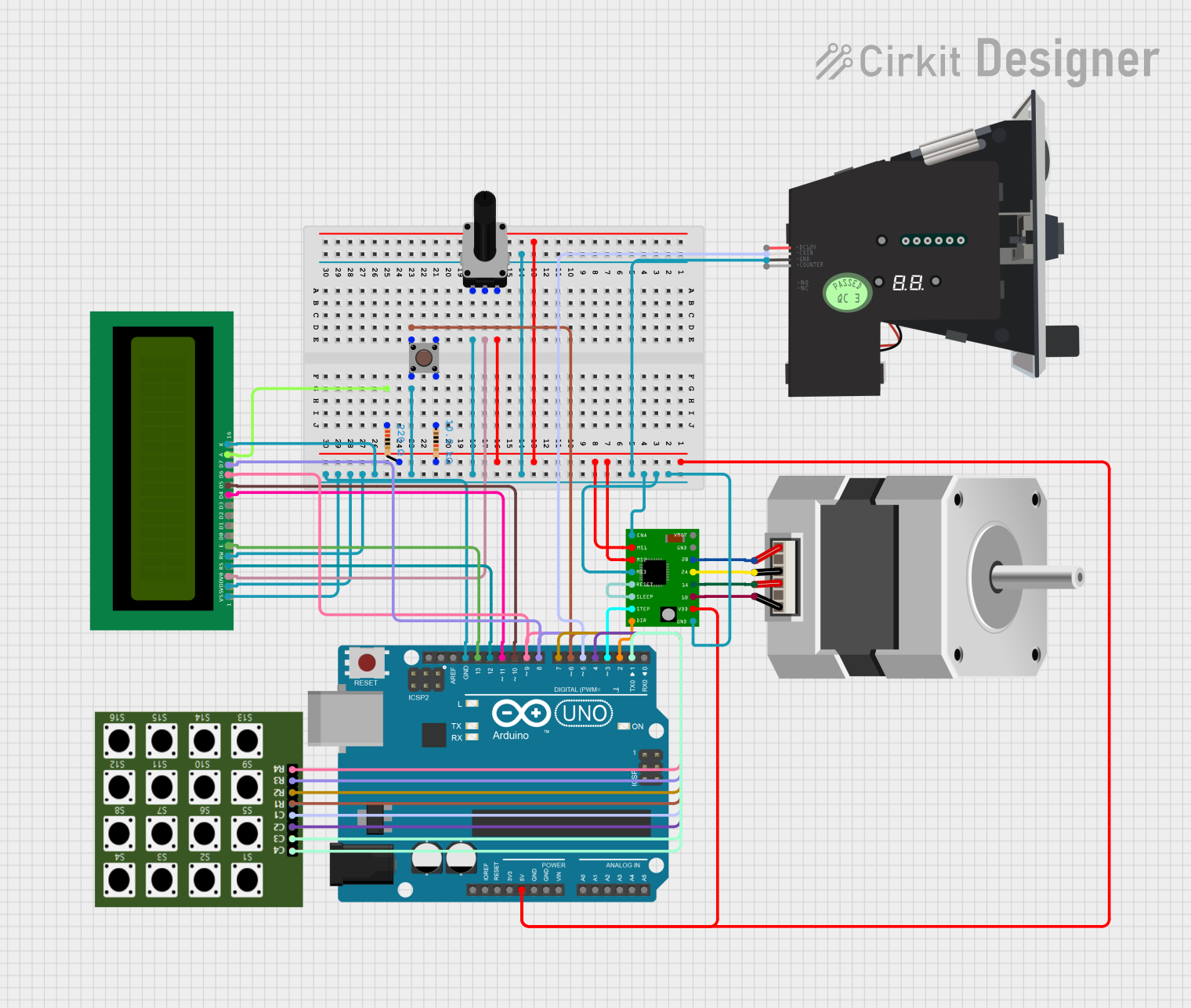
Circuit Documentation
Summary
This circuit involves an Arduino UNO microcontroller interfacing with various components including a stepper motor, a stepper motor driver, a rotary potentiometer, a pushbutton, resistors, an LCD display, a multi-coin acceptor, and a 4×4 keypad. The Arduino UNO controls the stepper motor via the A4988 stepper motor driver and displays information on the LCD. The rotary potentiometer and pushbutton provide user input, while the multi-coin acceptor and keypad handle coin input and user commands respectively.
Component List
Stepper Motor (Bipolar)
- Description: A bipolar stepper motor with four pins for controlling the motor coils.
- Pins: D, B, C, A
A4988 Stepper Motor Driver Carrier
- Description: A driver carrier for controlling a bipolar stepper motor.
- Pins: ENABLE, MS1, MS2, MS3, RESET, SLEEP, STEP, DIR, GND, VCC, 1B, 1A, 2A, 2B, VMOT
Arduino UNO
- Description: A microcontroller board based on the ATmega328P.
- Pins: UNUSED, IOREF, Reset, 3.3V, 5V, GND, Vin, A0, A1, A2, A3, A4, A5, SCL, SDA, AREF, D13, D12, D11, D10, D9, D8, D7, D6, D5, D4, D3, D2, D1, D0
Rotary Potentiometer
- Description: A variable resistor used to adjust voltage levels.
- Pins: leg1, wiper, leg2
- Properties: Resistance: 10k Ohms
Resistor (220 Ohms)
- Description: A resistor with a resistance of 220 Ohms.
- Pins: pin1, pin2
- Properties: Resistance: 220 Ohms
Resistor (10k Ohms)
- Description: A resistor with a resistance of 10k Ohms.
- Pins: pin1, pin2
- Properties: Resistance: 10k Ohms
Pushbutton
- Description: A simple pushbutton switch.
- Pins: Pin 3 (out), Pin 4 (out), Pin 1 (in), Pin 2 (in)
16X2 LCD
- Description: A 16x2 character LCD display.
- Pins: VSS, VDD, V0, RS, RW, E, D1, D0, D2, D3, D4, D6, D5, D7, A, K
Multi Coin Acceptor
- Description: A device that accepts multiple types of coins.
- Pins: COIN, DC12V, GND, COUNTER
4×4 Keypad
- Description: A keypad with 4 rows and 4 columns.
- Pins: C3, C2, C4, C1, R1, R2, R3, R4
Wiring Details
Stepper Motor (Bipolar)
- D connected to 1B of A4988 Stepper Motor Driver Carrier
- B connected to 1A of A4988 Stepper Motor Driver Carrier
- C connected to 2A of A4988 Stepper Motor Driver Carrier
- A connected to 2B of A4988 Stepper Motor Driver Carrier
A4988 Stepper Motor Driver Carrier
- VCC connected to 5V of Arduino UNO
- GND connected to GND of Arduino UNO
- MS1 connected to 5V of Arduino UNO
- MS2 connected to 5V of Arduino UNO
- MS3 connected to GND of Arduino UNO
- ENABLE connected to GND of Arduino UNO
- RESET connected to SLEEP of A4988 Stepper Motor Driver Carrier
- STEP connected to D3 of Arduino UNO
- DIR connected to D2 of Arduino UNO
- 1B connected to D of Stepper Motor (Bipolar)
- 1A connected to B of Stepper Motor (Bipolar)
- 2A connected to C of Stepper Motor (Bipolar)
- 2B connected to A of Stepper Motor (Bipolar)
Arduino UNO
- 5V connected to VCC of A4988 Stepper Motor Driver Carrier
- GND connected to GND of A4988 Stepper Motor Driver Carrier
- D3 connected to STEP of A4988 Stepper Motor Driver Carrier
- D2 connected to DIR of A4988 Stepper Motor Driver Carrier
- D6 connected to R1 of 4×4 Keypad
- D12 connected to RS of 16X2 LCD
- D13 connected to E of 16X2 LCD
- D11 connected to D4 of 16X2 LCD
- D9 connected to D6 of 16X2 LCD
- D10 connected to D5 of 16X2 LCD
- D8 connected to D7 of 16X2 LCD
- D7 connected to R2 of 4×4 Keypad
- D5 connected to C1 of 4×4 Keypad
- D4 connected to C2 of 4×4 Keypad
- D1 connected to C3 of 4×4 Keypad
Rotary Potentiometer
- leg2 connected to pin2 of Resistor (220 Ohms)
- leg2 connected to pin2 of Resistor (10k Ohms)
- leg2 connected to VCC of A4988 Stepper Motor Driver Carrier
- leg2 connected to 5V of Arduino UNO
- wiper connected to V0 of 16X2 LCD
- leg1 connected to Pin 2 (in) of Pushbutton
- leg1 connected to GND of A4988 Stepper Motor Driver Carrier
- leg1 connected to MS3 of A4988 Stepper Motor Driver Carrier
- leg1 connected to ENABLE of A4988 Stepper Motor Driver Carrier
- leg1 connected to GND of Multi Coin Acceptor
- leg1 connected to K of 16X2 LCD
- leg1 connected to RW of 16X2 LCD
- leg1 connected to VDD of 16X2 LCD
- leg1 connected to VSS of 16X2 LCD
- leg1 connected to GND of Arduino UNO
Resistor (220 Ohms)
- pin1 connected to A of 16X2 LCD
Resistor (10k Ohms)
- pin1 connected to Pin 4 (out) of Pushbutton
Pushbutton
- Pin 1 (in) connected to R1 of 4×4 Keypad
- Pin 1 (in) connected to D6 of Arduino UNO
- Pin 2 (in) connected to leg1 of Rotary Potentiometer
- Pin 4 (out) connected to pin1 of Resistor (10k Ohms)
16X2 LCD
- V0 connected to wiper of Rotary Potentiometer
- RS connected to D12 of Arduino UNO
- E connected to D13 of Arduino UNO
- D4 connected to D11 of Arduino UNO
- D6 connected to D9 of Arduino UNO
- D5 connected to D10 of Arduino UNO
- D7 connected to D8 of Arduino UNO
- A connected to pin1 of Resistor (220 Ohms)
- K connected to leg1 of Rotary Potentiometer
- RW connected to leg1 of Rotary Potentiometer
- VDD connected to leg1 of Rotary Potentiometer
- VSS connected to leg1 of Rotary Potentiometer
Multi Coin Acceptor
- GND connected to leg1 of Rotary Potentiometer
- COIN connected to C1 of 4×4 Keypad
- **CO