
Arduino Mega 2560 Controlled DC Motor System with BTS7960 Motor Drivers and Step-Up Boost Converter
View and Edit Project In Cirkit Designer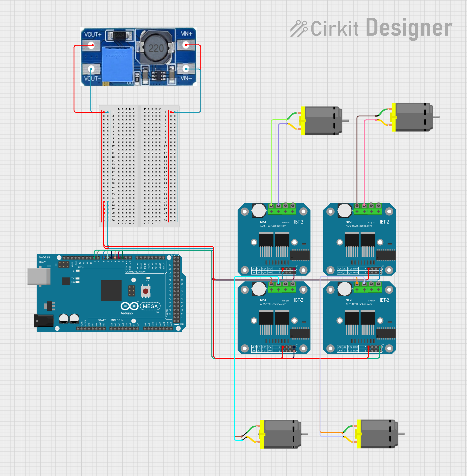
Circuit Documentation
Summary
This circuit involves an Arduino Mega 2560 microcontroller, four DC motors, a step-up boost power converter, and four BTS7960 motor drivers. The Arduino Mega 2560 controls the motor drivers, which in turn drive the DC motors. The step-up boost power converter provides the necessary voltage to the motor drivers.
Component List
Arduino Mega 2560
- Description: A microcontroller board based on the ATmega2560.
- Pins: IOREF, RESET, 3V3, 5V, GND, VIN, A0-A15, D21/SCL, D20/SDA, D19/RX1, D18/TX1, D17 PWM/RX2, D16 PWM/TX2, D15/RX3, D14/TX3, D0 RX0, D1 TX0, D2 PWM, D3 PWM, D4 PWM, D5 PWM, D6 PWM, D7 PWM, D8 PWM, D9 PWM, D10 PWM, D11 PWM, D12 PWM, D13 PWM, AREF, SDA, SCL, D52, D50, D48, D46, D44, D42, D40, D38, D36, D34, D32, D30, D28, D26, D24, D22, D53, D51, D49, D47, D45, D43, D41, D39, D37, D35, D33, D31, D29, D27, D25, D23, 6swdw
DC Motor
- Description: A simple DC motor with two pins.
- Pins: pin 1, pin 2
Step Up Boost Power Converter, Adjustable Voltage Regulator
- Description: A power converter that steps up the input voltage to a higher output voltage.
- Pins: VOUT+, VOUT-, VIN+, VIN-
BTS7960 Motor Driver
- Description: A high-current motor driver with 12 pins.
- Pins: Pin 1, Pin 2, Pin 3, Pin 4, Pin 5, Pin 6, Pin 7, Pin 8, Pin 9, Pin 10, Pin 11, Pin 12
Wiring Details
Arduino Mega 2560
- D2 PWM is connected to Pin 4 of a BTS7960 Motor Driver.
- D3 PWM is connected to Pin 8 of a BTS7960 Motor Driver.
- D4 PWM is connected to Pin 4 of another BTS7960 Motor Driver.
- D5 PWM is connected to Pin 8 of another BTS7960 Motor Driver.
- D6 PWM is connected to Pin 4 of another BTS7960 Motor Driver.
- D7 PWM is connected to Pin 8 of another BTS7960 Motor Driver.
- D8 PWM is connected to Pin 4 of another BTS7960 Motor Driver.
- D9 PWM is connected to Pin 8 of another BTS7960 Motor Driver.
DC Motor
pin 1 of the first DC Motor is connected to Pin 12 of a BTS7960 Motor Driver.
pin 2 of the first DC Motor is connected to Pin 11 of a BTS7960 Motor Driver.
pin 1 of the second DC Motor is connected to Pin 12 of another BTS7960 Motor Driver.
pin 2 of the second DC Motor is connected to Pin 11 of another BTS7960 Motor Driver.
pin 1 of the third DC Motor is connected to Pin 12 of another BTS7960 Motor Driver.
pin 2 of the third DC Motor is connected to Pin 11 of another BTS7960 Motor Driver.
pin 1 of the fourth DC Motor is connected to Pin 12 of another BTS7960 Motor Driver.
pin 2 of the fourth DC Motor is connected to Pin 11 of another BTS7960 Motor Driver.
Step Up Boost Power Converter, Adjustable Voltage Regulator
- VOUT+ is connected to Pin 5 of all four BTS7960 Motor Drivers.
- VOUT- is connected to Pin 1 of all four BTS7960 Motor Drivers.
- VIN+ and VIN- are not connected in the provided net list.
BTS7960 Motor Driver
- Pin 4 of the first BTS7960 Motor Driver is connected to D2 PWM of the Arduino Mega 2560.
- Pin 8 of the first BTS7960 Motor Driver is connected to D3 PWM of the Arduino Mega 2560.
- Pin 4 of the second BTS7960 Motor Driver is connected to D4 PWM of the Arduino Mega 2560.
- Pin 8 of the second BTS7960 Motor Driver is connected to D5 PWM of the Arduino Mega 2560.
- Pin 4 of the third BTS7960 Motor Driver is connected to D6 PWM of the Arduino Mega 2560.
- Pin 8 of the third BTS7960 Motor Driver is connected to D7 PWM of the Arduino Mega 2560.
- Pin 4 of the fourth BTS7960 Motor Driver is connected to D8 PWM of the Arduino Mega 2560.
- Pin 8 of the fourth BTS7960 Motor Driver is connected to D9 PWM of the Arduino Mega 2560.
Documented Code
Arduino Mega 2560 Code (sketch.ino)
void setup() {
  // put your setup code here, to run once:

}

void loop() {
  // put your main code here, to run repeatedly:

}
Additional Documentation (documentation.txt)
This documentation provides a comprehensive overview of the circuit, including a summary, detailed component list, wiring details, and the code used in the Arduino Mega 2560 microcontroller.