
Circuit Documentation
Summary
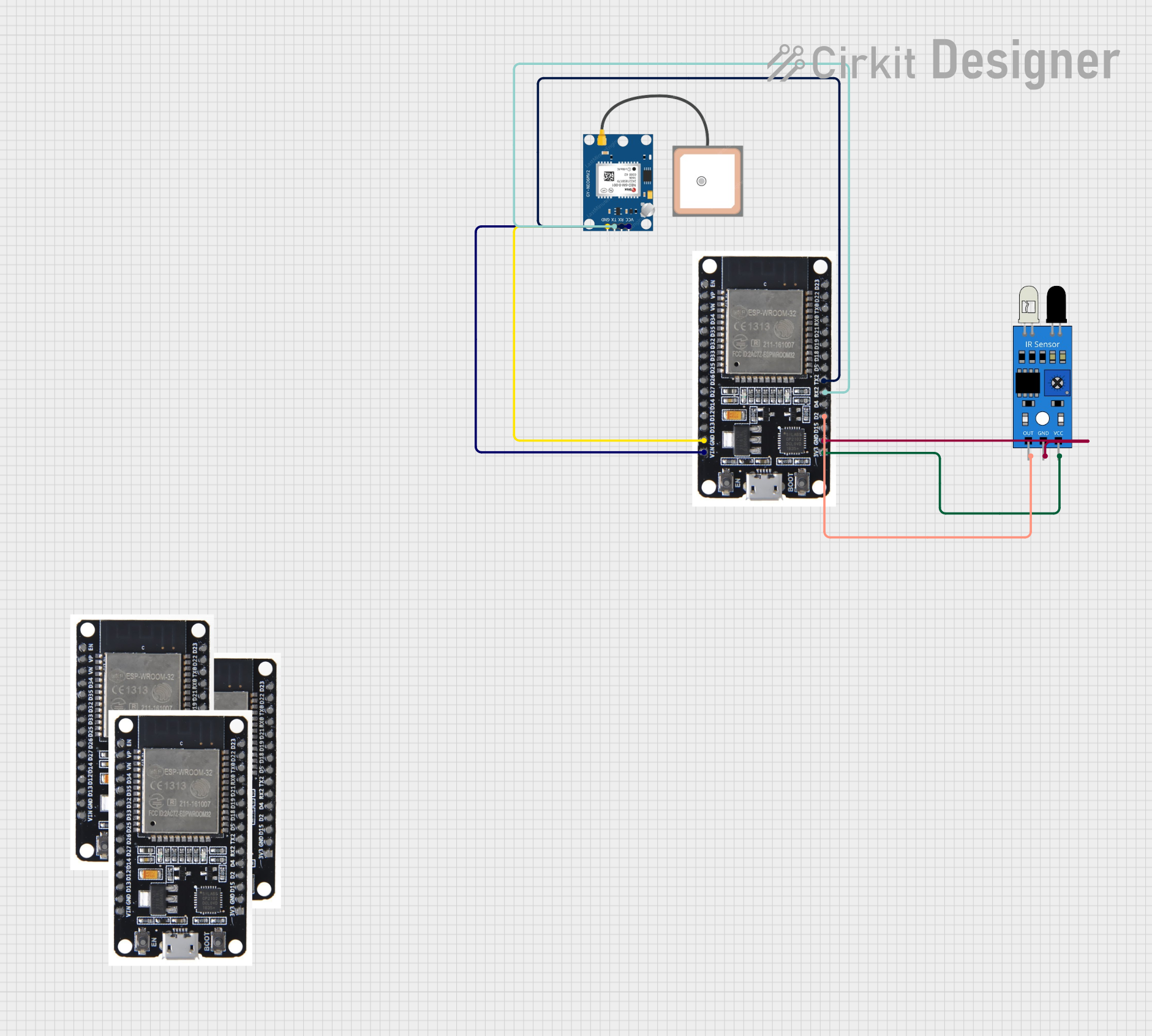
This circuit involves multiple ESP32 microcontrollers interfacing with a GPS NEO 6M module and an IR sensor. The ESP32 microcontrollers are used to process data from the GPS module and the IR sensor. The connections between the components are detailed below.
Component List
ESP32
- Description: A powerful microcontroller with Wi-Fi and Bluetooth capabilities.
- Pins: EN, VP, VN, D34, D35, D32, D33, D25, D26, D27, D14, D12, D13, GND, VIN, 3V3, D15, D2, D4, RX2, TX2, D5, D18, D19, D21, RX0, TX0, D22, D23, BOOT
GPS NEO 6M
- Description: A GPS module used for obtaining location data.
- Pins: VCC, RX, TX, GND
IR Sensor
- Description: An infrared sensor used for detecting objects.
- Pins: out, gnd, vcc
Wiring Details
ESP32
GND is connected to:
- GND of GPS NEO 6M
- gnd of IR Sensor
VIN is connected to:
- VCC of GPS NEO 6M
3V3 is connected to:
- vcc of IR Sensor
D2 is connected to:
- out of IR Sensor
RX2 is connected to:
- TX of GPS NEO 6M
TX2 is connected to:
- RX of GPS NEO 6M
GPS NEO 6M
GND is connected to:
- GND of ESP32
VCC is connected to:
- VIN of ESP32
RX is connected to:
- TX2 of ESP32
TX is connected to:
- RX2 of ESP32
IR Sensor
gnd is connected to:
- GND of ESP32
vcc is connected to:
- 3V3 of ESP32
out is connected to:
- D2 of ESP32
Code
There is no code provided for the microcontrollers in this circuit.
This documentation provides a comprehensive overview of the components and their interconnections in the circuit. Each component's role and wiring details are clearly outlined to facilitate understanding and replication of the circuit.