Cirkit Designer
Your all-in-one circuit design IDE
Home /
Project Documentation
ESP32-Controlled Smart Home Lighting System with IR and Manual Switches
Circuit Documentation
Summary
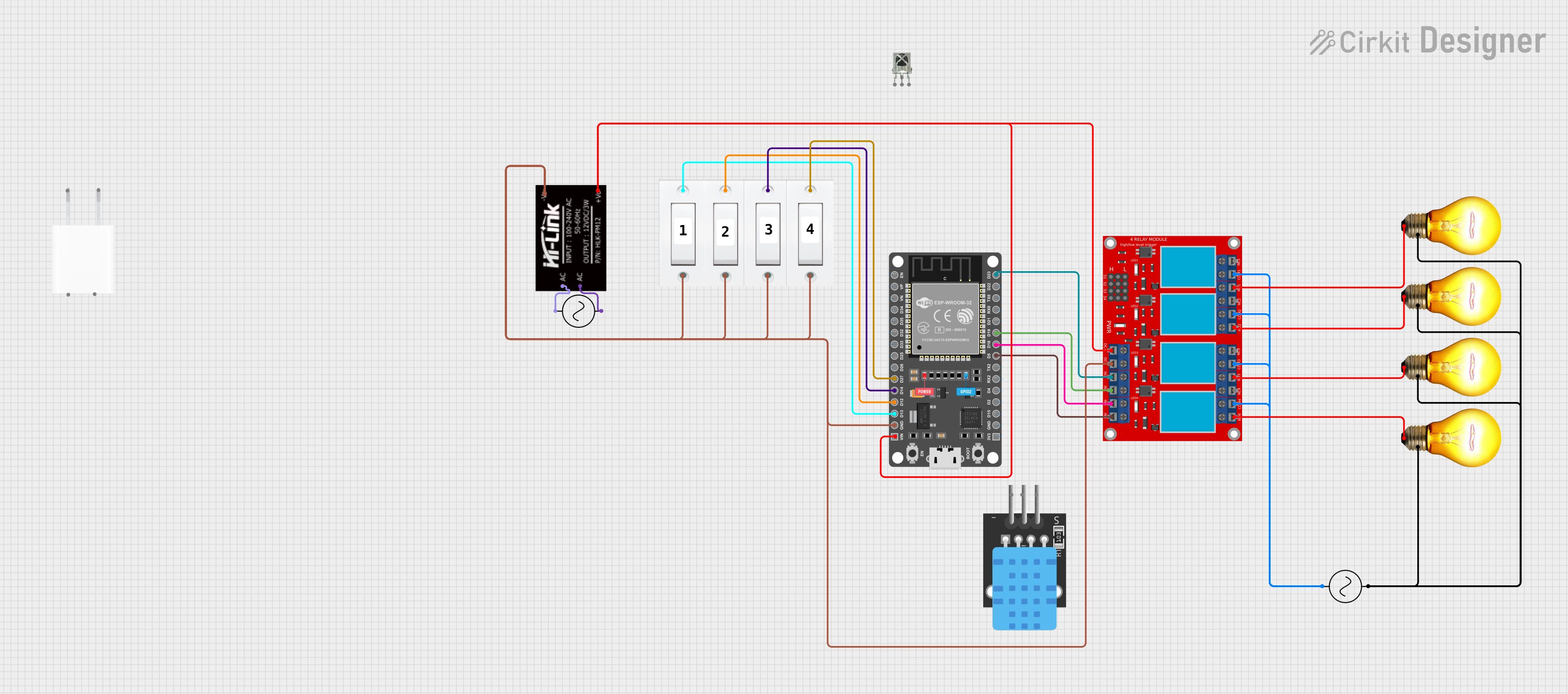
The circuit in question is designed to control four AC bulbs via a 4-channel relay module, which is interfaced with an ESP32 DEVKIT V1 microcontroller. The ESP32 is also connected to an IR receiver for remote control functionality and several flush switches for manual control. The circuit is powered by an AC supply, with a HLK-PM12 module converting AC to a stable 5V DC supply for the microcontroller and relay module. The ESP32 runs embedded code that allows for IoT connectivity, sensor reading, and control of the relays based on IR signals or manual switch input.
Component List
- 4 Channel Relay Module: A module with four relays that can control high power devices like AC bulbs. Each relay has a Normally Open (N.O.), Common (COM), and Normally Closed (N.C.) terminal.
- VS1838B IR Receiver: An infrared receiver that captures IR signals from a remote control.
- ESP 32 DEVKIT V1 (30 pins): A microcontroller with WiFi capabilities for IoT applications.
- AC Bulb: A standard AC-powered light bulb.
- Ac Supply: Provides the AC power to the circuit.
- Flush Switch: A push-button switch used for manual control of the relays.
- 5V Adapter: Converts AC power to 5V DC.
- HLK-PM12: A compact power supply module that converts 110-220V AC to 12V DC.
Wiring Details
4 Channel Relay Module
- N.O. 4, N.O. 3, N.O. 2, N.O. 1: Connected to the positive terminal of AC Bulbs.
- COM 4, COM 3, COM 2, COM 1: Interconnected and connected to the positive terminal of the Ac Supply.
- VCC+: Connected to the +V0 of HLK-PM12.
- VCC- (GND): Connected to the -V0 of HLK-PM12.
- IN 1, IN 2, IN 3, IN 4: Controlled by GPIOs D23, D19, D18, D5 of the ESP32 respectively.
VS1838B IR Receiver
- OUT: Not specified in the net list.
- GND: Not specified in the net list.
- VCC: Not specified in the net list.
ESP 32 DEVKIT V1 (30 pins)
- VIN: Connected to the +V0 of HLK-PM12.
- GND: Connected to the -V0 of HLK-PM12 and GND of Flush Switches.
- D23, D19, D18, D5: Control the IN 1, IN 2, IN 3, IN 4 of the 4 Channel Relay Module.
- D27, D14, D12, D13: Connected to the VCC of Flush Switches.
AC Bulb
- P: Connected to the N.O. terminals of the 4 Channel Relay Module.
- N: Interconnected among all bulbs and connected to the negative terminal of the Ac Supply.
Ac Supply
- +ve: Connected to the COM terminals of the 4 Channel Relay Module and the AC terminal of HLK-PM12.
- -ve: Connected to the N terminals of the AC Bulbs and the AC terminal of HLK-PM12.
Flush Switch
- GND: Connected to the GND of ESP32.
- VCC: Connected to the GPIOs D27, D14, D12, D13 of the ESP32.
HLK-PM12
- +V0: Provides 5V to the VCC+ of the 4 Channel Relay Module and VIN of ESP32.
- -V0: Connected to the VCC- (GND) of the 4 Channel Relay Module and GND of ESP32.
- AC: Connected to the +ve and -ve of the Ac Supply.
Documented Code
#include <ArduinoIoTCloud.h>
#include <Arduino_ConnectionHandler.h>
#include <DHT.h>
#include <IRremote.h>

// Credentials and settings (fill with your data)
const char DEVICE_LOGIN_NAME[]  = ""; // Enter DEVICE ID
const char SSID[]               = ""; // Enter WiFi SSID (name)
const char PASS[]               = ""; // Enter WiFi password
const char DEVICE_KEY[]         = ""; // Enter Secret device password (Secret Key)

// Pin definitions
#define DHTPIN              4  // D4 pin connected with DHT
#define IR_RECV_PIN         35 // D35 pin connected with IR Receiver IC

// GPIO connected with Relays and switches
#define RelayPin1 23  // D23
#define RelayPin2 19  // D19
#define RelayPin3 18  // D18
#define RelayPin4 5   // D5

#define SwitchPin1 13 // D13
#define SwitchPin2 12 // D12
#define SwitchPin3 14 // D14
#define SwitchPin4 27 // D27

#define wifiLed    2  // D2

// DHT sensor type
#define DHTTYPE DHT11 // DHT 11

DHT dht(DHTPIN, DHTTYPE);
IRrecv irrecv(IR_RECV_PIN);
decode_results results;

// Toggle state for relays
int toggleState_1 = 0;
int toggleState_2 = 0;
int toggleState_3 = 0;
int toggleState_4 = 0;

// Switch State
bool SwitchState_1 = LOW;
bool SwitchState_2 = LOW;
bool SwitchState_3 = LOW;
bool SwitchState_4 = LOW;

// Sensor data
float temperature1 = 0;
float humidity1   = 0;
int   reconnectFlag = 0;

// Function declarations
void onLight1Change();
void onLight2Change();
void onLight3Change();
void onLight4Change();

// Cloud properties
CloudSwitch light1;
CloudSwitch light2;
CloudSwitch light3;
CloudSwitch light4;
CloudTemperatureSensor temperature;

// Initialize cloud properties
void initProperties(){
  ArduinoCloud.setBoardId(DEVICE_LOGIN_NAME);
  ArduinoCloud.setSecretDeviceKey(DEVICE_KEY);
  ArduinoCloud.addProperty(light1, READWRITE, ON_CHANGE, onLight1Change);
  ArduinoCloud.addProperty(light2, READWRITE, ON_CHANGE, onLight2Change);
  ArduinoCloud.addProperty(light3, READWRITE, ON_CHANGE, onLight3Change);
  ArduinoCloud.addProperty(light4, READWRITE, ON_CHANGE, onLight4Change);
  ArduinoCloud.addProperty(temperature, READ, 8 * SECONDS, NULL); // Update temperature value after every 8 seconds
}

WiFiConnectionHandler ArduinoIoTPreferredConnection(SSID, PASS);

// Read sensor data
void readSensor(){
  float h = dht.readHumidity();
  float t = dht.readTemperature(); // or dht.readTemperature(true) for Fahrenheit

  if (isnan(h) || isnan(t)) {
    Serial.println("Failed to read from DHT sensor!");
    return;
  }
  else {
    humidity1 = h;
    temperature = t;
  }
}

// Send sensor data
void sendSensor()
{
  readSensor();
}

// IR remote control
void ir_remote_control(){
  if (irrecv.decode(&results)) {
    switch(results.value){
      case 0x80BF49B6:  relayOnOff(1); light1 = toggleState_1; break; // Update the HEX-code
      case 0x80BFC936:  relayOnOff(2); light2 = toggleState_2; break; // Update the HEX-code
      case 0x80BF33CC:  relayOnOff(3); light3 = toggleState_3; break; // Update the HEX-code
      case 0x80BF718E:  relayOnOff(4); light4 = toggleState_4; break; // Update the HEX-code
      default : break;
    }
    irrecv.resume();
  }
}

// Relay control function
void relayOnOff(int relay) {
  switch (relay) {
    case 1:
      if (toggleState_1 == 0) {
        digitalWrite(RelayPin1, LOW); // turn on relay 1
        toggleState_1 = 1;
        Serial.println("Device1 ON");
      }
      else {
        digitalWrite(RelayPin1, HIGH); // turn off relay 1
        toggleState_1 = 0;
        Serial.println("Device1 OFF");
      }
      delay(100);
      break;
    case 2:
      if (toggleState_2 == 0) {
        digitalWrite(RelayPin2, LOW); // turn on relay 2
        toggleState_2 = 1;
        Serial.println("Device2 ON");
      }
      else {
        digitalWrite(RelayPin2, HIGH); // turn off relay 2
        toggleState_2 = 0;
        Serial.println("Device2 OFF");
      }
      delay(100);
      break;
    case 3:
      if (toggleState_3 == 0) {
        digitalWrite(RelayPin3, LOW); // turn on relay 3
        toggleState_3 = 1;
        Serial.println("Device3 ON");
      } else {