Arduino Nano-Based Smart Irrigation System with Wi-Fi Control and LCD Display
Circuit Documentation
Summary
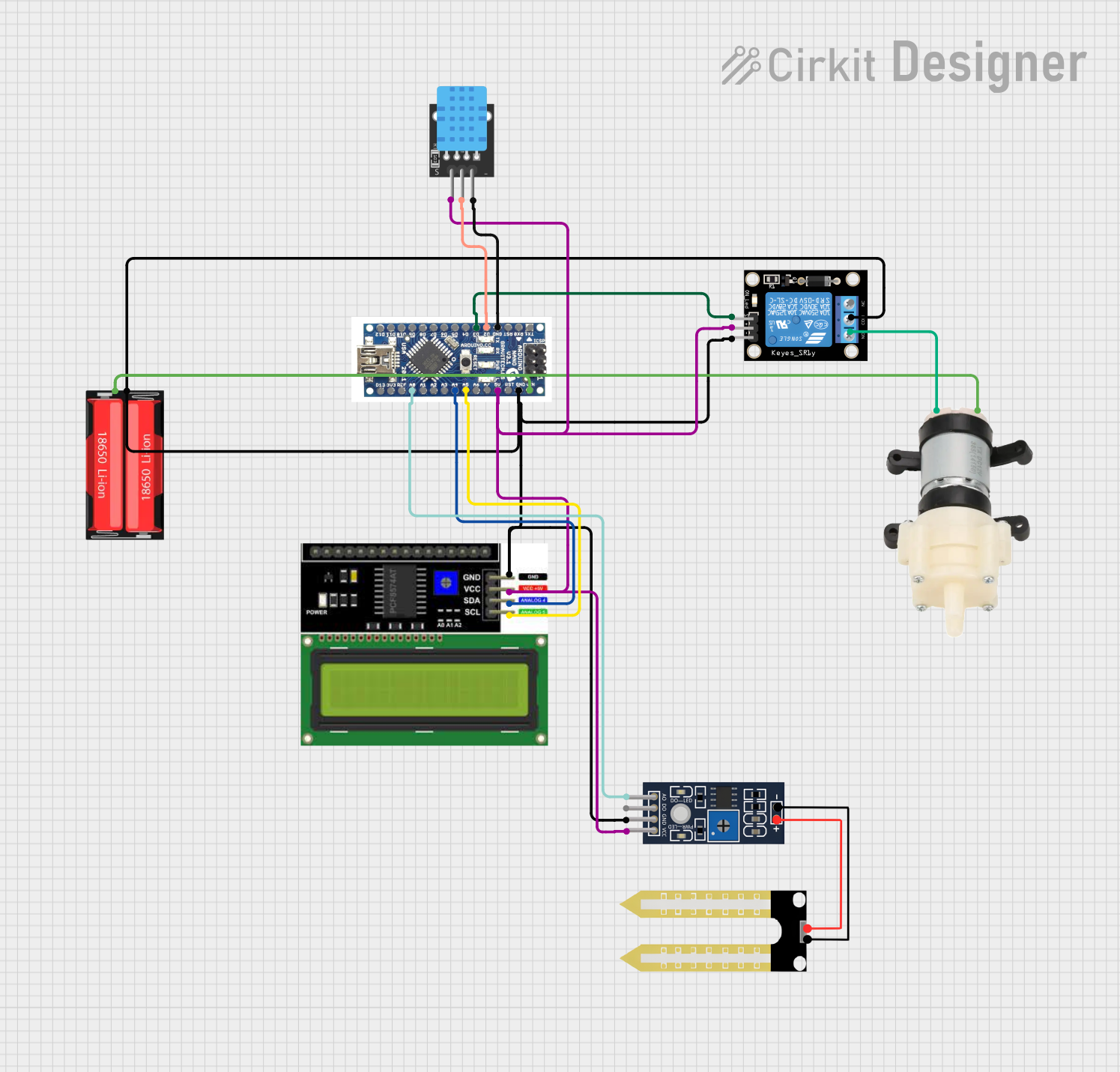
This document provides a detailed overview of a circuit designed using an Arduino Nano microcontroller. The circuit includes various sensors and modules such as a relay module, DHT11 temperature and humidity sensor, LCD I2C display, humidity sensor, and a mini diaphragm water pump. The circuit is powered by a 18650 Li-Ion battery. The Arduino Nano controls the relay module, reads data from the sensors, and displays information on the LCD. The water pump is controlled based on the sensor readings.
Component List
Arduino Nano
- Description: A small, complete, and breadboard-friendly board based on the ATmega328P.
- Pins: D12, D11, D10, D9, D8, D7, D6, D5, D4, D3, D2, GND, RST, RX0, TX1, D13, 3V3, REF, A0, A1, A3, A4, A5, A6, A7, 5V, VIN
Relay Module 1 Channel
- Description: A single-channel relay module used to control high voltage devices.
- Pins: S, 5V, GND, NC, COM, NO
DHT11
- Description: A temperature and humidity sensor.
- Pins: 5V, S, GND
LCD I2C Display
- Description: A 16x2 character LCD display with I2C interface.
- Pins: GND, VCC, SDA, SCL
Humidity YL-69
- Description: A soil moisture sensor.
- Pins: A0, D0, GND, VCC
Mini Diaphragm Water Pump
- Description: A small water pump used for irrigation.
- Pins: Positive (+), Negative (-)
18650 Li-Ion
- Description: A rechargeable lithium-ion battery.
- Pins: Positive, Negative
Wiring Details
Arduino Nano
- D3 connected to Relay Module 1 Channel (S)
- D2 connected to DHT11 (S)
- GND connected to DHT11 (GND)
- A0 connected to Humidity YL-69 (A0)
- A4 connected to LCD I2C Display (SDA)
- A5 connected to LCD I2C Display (SCL)
- 5V connected to LCD I2C Display (VCC), Relay Module 1 Channel (5V), Humidity YL-69 (VCC), DHT11 (5V)
- GND connected to LCD I2C Display (GND), Relay Module 1 Channel (GND), Relay Module 1 Channel (COM), 18650 Li-Ion (Negative), Humidity YL-69 (GND)
- VIN connected to Mini Diaphragm Water Pump (Positive (+)), 18650 Li-Ion (Positive)
Relay Module 1 Channel
- S connected to Arduino Nano (D3)
- 5V connected to Arduino Nano (5V)
- GND connected to Arduino Nano (GND)
- COM connected to Arduino Nano (GND)
- NO connected to Mini Diaphragm Water Pump (Negative (-))
DHT11
- S connected to Arduino Nano (D2)
- GND connected to Arduino Nano (GND)
- 5V connected to Arduino Nano (5V)
LCD I2C Display
- SDA connected to Arduino Nano (A4)
- SCL connected to Arduino Nano (A5)
- VCC connected to Arduino Nano (5V)
- GND connected to Arduino Nano (GND)
Humidity YL-69
- A0 connected to Arduino Nano (A0)
- VCC connected to Arduino Nano (5V)
- GND connected to Arduino Nano (GND)
Mini Diaphragm Water Pump
- Positive (+) connected to Arduino Nano (VIN)
- Negative (-) connected to Relay Module 1 Channel (NO)
18650 Li-Ion
- Positive connected to Arduino Nano (VIN)
- Negative connected to Arduino Nano (GND)
Documented Code
Arduino Nano Code
// No code provided for Arduino Nano
LCD I2C Display Code
void setup() {
  // put your setup code here, to run once:
}

void loop() {
  // put your main code here, to run repeatedly:
}
Humidity YL-69 Code
// Define Blynk template and authentication
#define BLYNK_TEMPLATE_ID "TMPL6aciioChP"
#define BLYNK_TEMPLATE_NAME "cicekSula"
#define BLYNK_AUTH_TOKEN "lSiVlNDn6VZUBqE5Z7mvDbN-IFefbnKt"

// Include the library files
#include <LiquidCrystal_I2C.h>
#define BLYNK_PRINT Serial
#include <ESP8266WiFi.h>
#include <BlynkSimpleEsp8266.h>

// Initialize the LCD display
LiquidCrystal_I2C lcd(0x27, 16, 2);

char ssid[] = "Galaxy A21sC3B8"; // Enter your WiFi name
char pass[] = "uuwy2702";        // Enter your WiFi password

BlynkTimer timer;
bool Relay = 0;

// Define component pins
#define sensor A0
#define waterPump D3

void setup() {
  Serial.begin(9600);

  // Initialize water pump pin
  pinMode(waterPump, OUTPUT);
  digitalWrite(waterPump, HIGH);

  // Initialize LCD
  lcd.init();
  lcd.backlight();

  // Connect to Blynk
  Blynk.begin(BLYNK_AUTH_TOKEN, ssid, pass, "blynk.cloud", 80);

  // Display "System Loading" animation on LCD
  lcd.setCursor(1, 0);
  lcd.print("System Loading");
  for (int a = 0; a <= 15; a++) {
    lcd.setCursor(a, 1);
    lcd.print(".");
    delay(500);
  }
  lcd.clear();

  // Call the soil moisture sensor function every 100ms
  timer.setInterval(100L, soilMoistureSensor);
}

// Button value control
BLYNK_WRITE(V1) {
  Relay = param.asInt();

  if (Relay == 1) {
    digitalWrite(waterPump, LOW);
    lcd.setCursor(0, 1);
    lcd.print("Motor is ON ");
  } else {
    digitalWrite(waterPump, HIGH);
    lcd.setCursor(0, 1);
    lcd.print("Motor is OFF");
  }
}

// Get soil moisture values
void soilMoistureSensor() {
  int value = analogRead(sensor);
  value = map(value, 0, 1024, 0, 100);
  value = (value - 100) * -1;

  // Send soil moisture value to Blynk app
  Blynk.virtualWrite(V0, value);

  // Display soil moisture value on LCD
  lcd.setCursor(0, 0);
  lcd.print("Moisture :");
  lcd.print(value);
  lcd.print(" ");
}

void loop() {
  Blynk.run();  // Run the Blynk library
  timer.run();  // Run the Blynk timer
}
18650 Li-Ion Code
void setup() {
  // put your setup code here, to run once:
}

void loop() {
  // put your main code here, to run repeatedly:
}
This document provides a comprehensive overview of the circuit, including the components used, their wiring details, and the code for the microcontrollers.