
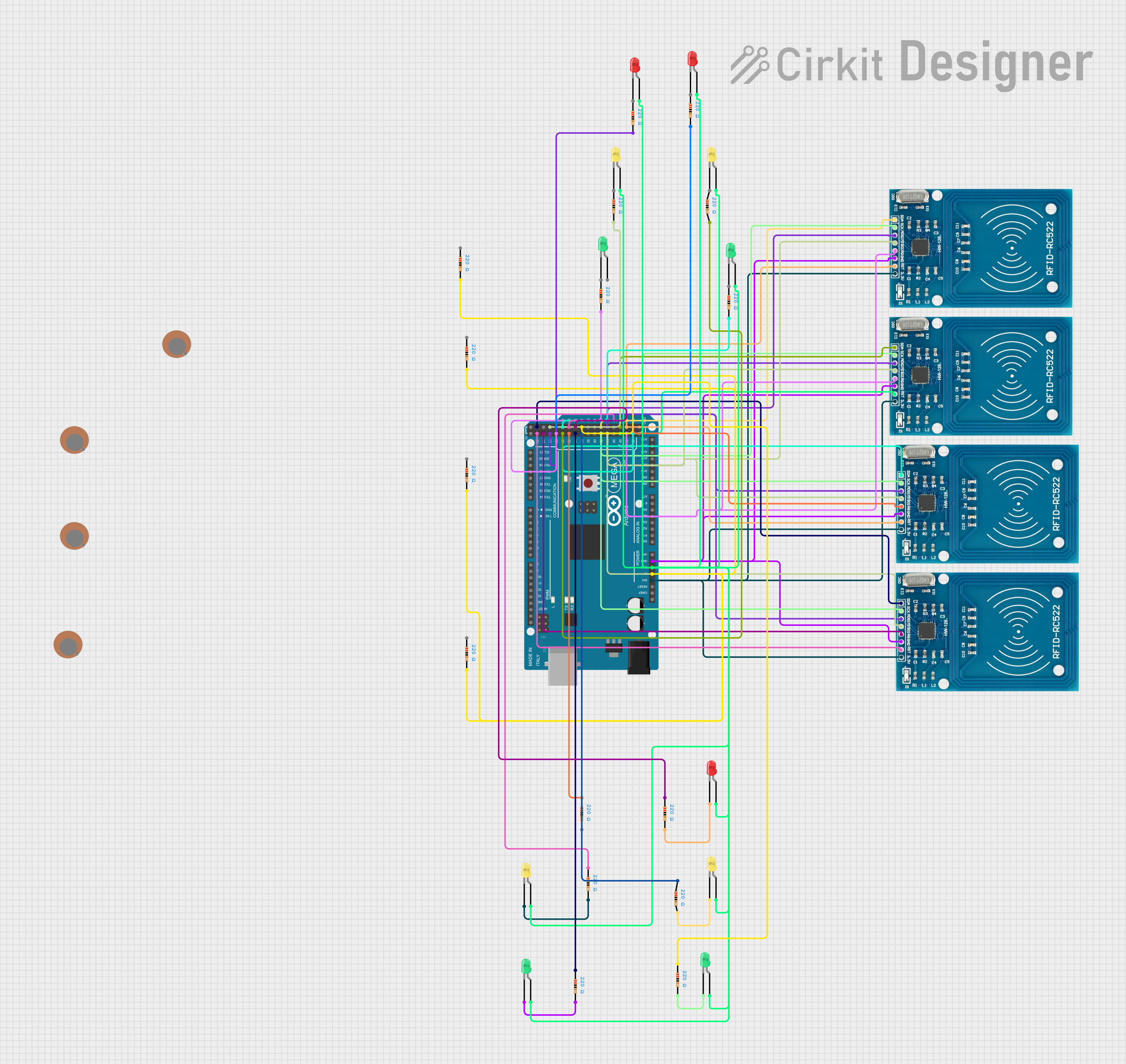
Circuit Documentation
Summary
This circuit involves an Arduino Mega 2560 microcontroller interfacing with multiple LEDs, resistors, RFID-RC522 modules, and piezo sensors. The circuit is designed to demonstrate basic LED control, RFID communication, and sensor integration.
Component List
LED: Two Pin (green)
- Pins: cathode, anode
- Description: Green LED
- Purpose: Visual indicator
LED: Two Pin (red)
- Pins: cathode, anode
- Description: Red LED
- Purpose: Visual indicator
LED: Two Pin (yellow)
- Pins: cathode, anode
- Description: Yellow LED
- Purpose: Visual indicator
Resistor
- Pins: pin1, pin2
- Description: 220 Ohms resistor
- Purpose: Current limiting for LEDs
RFID-RC522
- Pins: VCC (3.3V), RST, GND, IRQ, MISO, MOSI, SCK, SDA
- Description: RFID reader module
- Purpose: Reading RFID tags
Arduino Mega 2560
- Pins: IOREF, RESET, 3V3, 5V, GND, VIN, A0-A15, D0-D53, AREF, SDA, SCL
- Description: Microcontroller board
- Purpose: Central control unit
Piezo Sensor
- Pins: +, -
- Description: Piezoelectric sensor
- Purpose: Detecting vibrations
Wiring Details
Arduino Mega 2560
3V3
- Connected to VCC (3.3V) of all RFID-RC522 modules
5V
- Connected to pin2 of multiple resistors
GND
- Connected to anode of multiple LEDs
- Connected to GND of all RFID-RC522 modules
D52
- Connected to SDA of one RFID-RC522 module
D50
- Connected to IRQ of two RFID-RC522 modules
D48
- Connected to RST of one RFID-RC522 module
D44
- Connected to MISO of all RFID-RC522 modules
D42
- Connected to SCK of all RFID-RC522 modules
D36
- Connected to pin1 of one resistor
D34
- Connected to pin1 of one resistor
D32
- Connected to pin1 of one resistor
D30
- Connected to pin2 of one resistor
D28
- Connected to pin2 of one resistor
D26
- Connected to pin2 of one resistor
D24
- Connected to IRQ of one RFID-RC522 module
D22
- Connected to RST of one RFID-RC522 module
D53
- Connected to IRQ of one RFID-RC522 module
D51
- Connected to RST of two RFID-RC522 modules
D49
- Connected to SDA of one RFID-RC522 module
D45
- Connected to MOSI of all RFID-RC522 modules
D43
- Connected to SDA of one RFID-RC522 module
D37
- Connected to pin1 of one resistor
D35
- Connected to pin1 of one resistor
D33
- Connected to pin1 of one resistor
D31
- Connected to pin2 of one resistor
D29
- Connected to pin2 of one resistor
D27
- Connected to pin2 of one resistor
D23
- Connected to SDA of one RFID-RC522 module
LEDs
Green LED
- Cathode connected to pin2 of one resistor
- Anode connected to GND of Arduino Mega 2560
Red LED
- Cathode connected to pin2 of one resistor
- Anode connected to GND of Arduino Mega 2560
Yellow LED
- Cathode connected to pin2 of one resistor
- Anode connected to GND of Arduino Mega 2560
Resistors
- 220 Ohms Resistor
- Pin1 connected to various digital pins of Arduino Mega 2560
- Pin2 connected to cathode of various LEDs and 5V of Arduino Mega 2560
RFID-RC522
VCC (3.3V)
- Connected to 3V3 of Arduino Mega 2560
GND
- Connected to GND of Arduino Mega 2560
SDA
- Connected to various digital pins of Arduino Mega 2560
IRQ
- Connected to various digital pins of Arduino Mega 2560
RST
- Connected to various digital pins of Arduino Mega 2560
MISO
- Connected to D44 of Arduino Mega 2560
MOSI
- Connected to D45 of Arduino Mega 2560
SCK
- Connected to D42 of Arduino Mega 2560
Piezo Sensors
+
- Not connected in the provided net list
-
- Not connected in the provided net list
Documented Code
sketch.ino
void setup() {
  // put your setup code here, to run once:

}

void loop() {
  // put your main code here, to run repeatedly:

}
documentation.txt